n today’s increasingly complex electromagnetic environments, the need for radiation hazards (RADHAZ) assessments and testing have reached critical importance. RADHAZ refers to the potential danger posed by radio frequency (RF) electromagnetic radiation. This term is commonly used in military, aerospace, and engineering contexts, especially in environments where high-powered RF transmitters are present. These dangers have traditionally been attributed to high-power intentional transmission equipment such as radars and long-range communications. However, low-power RF transmitters operating at close distances can also cause harm to personnel, ignite fuel, and initiate or disable electrically initiated explosive devices (EIDs).
This article will examine each of the three primary hazard areas covered by a RADHAZ assessment and dive into how these assessments are generally conducted. These hazard assessment areas cover:
- HERP (hazards of electromagnetic radiation to personnel)
- HERO (hazards of electromagnetic radiation to ordnance)
- HERF (hazards of electromagnetic radiation to fuel)
The life vest activations were reported during early operational deployments of these ships, suggesting the incidents likely occurred between 1987 and 1992, a period when HERO testing protocols were still evolving and the electromagnetic environment aboard Aegis ships was being actively characterized. While this event did not result in a catastrophic loss of life, it certainly depicts the threat electromagnetic radiation presents on ordnance devices, as well as the importance of well-executed modernized electromagnetic control plans.
Today, the HERO risk has evolved due to the gradual implementation of extremely powerful communications and radar equipment that radiate high levels of EM energy. This, coupled with the rapid deployment of advanced technologies consisting of EM sensitive, low-power electronics, is increasing HERO concerns to new levels. As a result of these growing risks, each service branch has placed an emphasis on verifying that all electrically initiated ordnance devices provide sufficient protection against their intended electromagnetic environment (EME), and that their performance is quantified through testing and/or analysis.
- HERO SAFE ORDNANCE
- HERO SUSCEPTIBLE ORDNANCE
- HERO UNSAFE ORDNANCE
- HERO UNRELIABLE ORDNANCE
While basic HERO requirements for design and performance verification are found in MIL‑STD-464 and other military standards, military service branches (Army, Navy, and Air Force) have developed unique approaches to deal with HERO problems over time. These approaches typically reflect other factors, such as how services store, transport, and use ordnance to minimize hazards.
When operational electromagnetic environment (EME) levels exceed susceptibility thresholds, the services can opt to use different risk-reduction measures. For example, the Army or Air Force might stipulate a minimum separation distance between the susceptible ordnance and the offending transmitter, while limited space aboard naval platforms/systems might leave no other option for the Navy than to impose restrictions on the emissions of the offending transmitter.
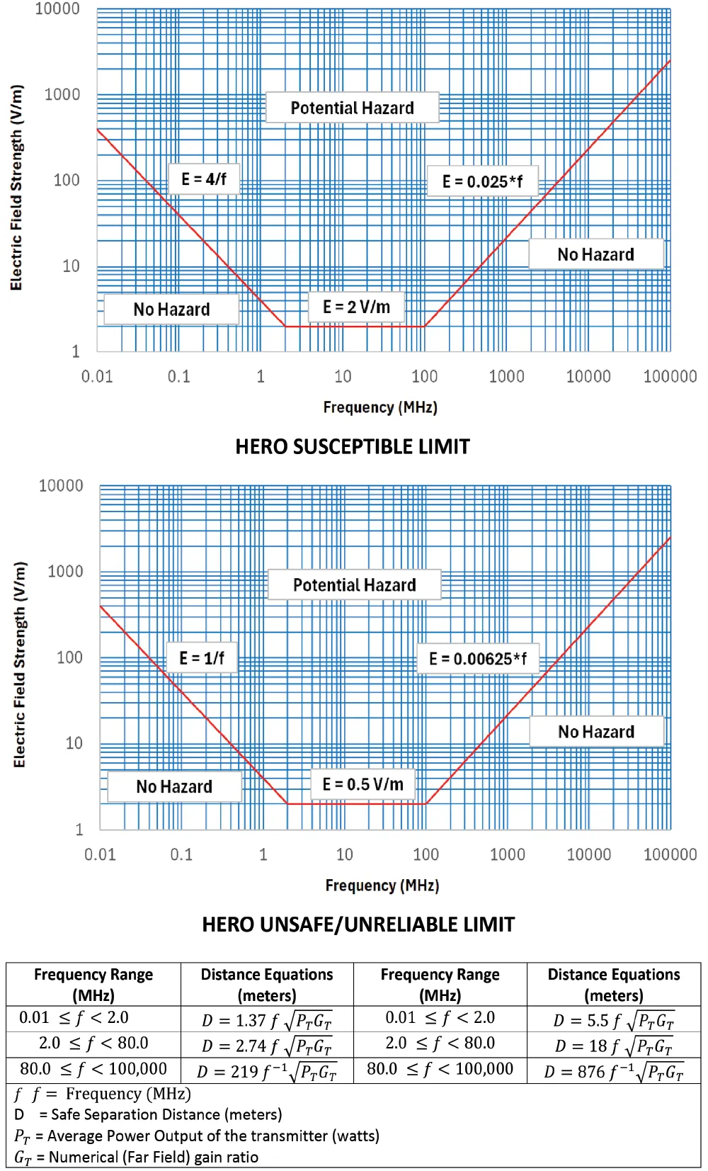
The HERO SUSCEPTIBLE and HERO UNSAFE limit curves shown in Figure 1 were derived from a tri-service effort; where the HERO test data for each of the services was used to develop composite “worst-case” curves that are now harmonized across all U.S. DoD service branches.
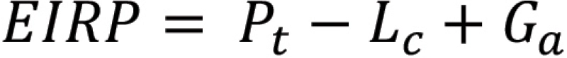
Pt = output power (dBm)
Lc = cable loss (dB)
Ga = antenna gain (dBi)
This data is generally gathered from the manufacturer’s commercial EMI/EMC compliance test reports or through physical measurements. Additional information, such as transmitter type, modulation scheme, characteristics, antenna pattern plots, typical orientation, use, and modes of operation, is not required but can be useful supporting data when compiling the report.
Typically, HERO power density levels are exceeded by high-power intentional transmitters with high-gain antennas. The maximum power density at a given distance or maximum distance to a given power density can be calculated using these far-field equations. In the far-field region, the power density is calculated within the 3 dB beam width of the transmit antenna using the following formula:


G = numerical antenna gain (unitless)
r = distance from the antenna (meters)
Since most antennas used in these applications are aperture-type and the power density levels are only exceeded at near-field distances (where power distribution is a function of illumination taper), far-field calculations are often found to be excessive. Further guidance can be found in NAVSEA OP 3565 Volume 1 on how to calculate the near-field gain reduction factor.
Examples of these RF devices include wireless laptops, handheld devices, tracking devices, and passive or active radio-frequency identification devices (RFID) using automatic identification technology (AIT) and operating at very low power (i.e., less than 1 watt). In these examples, relaxation of the standard ten-foot SSD distance down to a distance of zero feet between the antenna and ordnance item (excluding physical contact) can be determined using the HERO safe separation distance calculations shown in Figure 1.
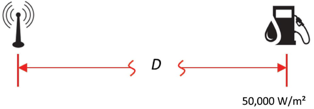
The SSD can also be calculated for HERF to establish the distance from a transmitting antenna where the power density will be approximately 5W/cm2. Much like with HERO SSDs, the actual separation distance between the transmitter and fuel should be established at a greater distance than calculated to ensure that the power density in the fueling area will be less than 5W/cm2.
The HERF SSD can be calculated using the following formula:

PD = desired power density (in W/m2) = 5 W/cm2 = 50,000 W/m2
D = distance (meters)
P = peak power (Watts)


PD = desired power density (in W/m2) = 5 W/cm2 = 50,000 W/m2
D = distance (meters)
P = peak power (Watts)

The transmitter must comply with the current DoD criteria for the protection of personnel against the effects of electromagnetic radiation. This DoD policy is currently found in DoDI 6055.11, and compliance is verified by test, analysis, or a combination of both.
Radar and ECM systems usually present the greatest potential personnel hazard due to their high transmit power levels and high-gain antenna characteristics, coupled with the potential of nearby personnel exposure. This poses the greatest risk to repair and facility maintenance personnel due to their frequent proximity to radiating elements and the need for rapid maintenance response.
In accordance with applicable standards, an RF hazard evaluation may be performed first by determining the SSD for personnel via calculations based on RF emitter characteristics or through measurement. Once the distance has been determined, an inspection is typically conducted in personnel access areas where exposure to the antenna’s main transmission beam is possible. Verification of appropriate warning signs, safety zones, and other precautionary measures, guidance manuals, and operating manuals is commonly required as part of the platform inspection process. Further technical guidance for assessing RF hazards can also be found in the Air Force AFRL-SA-WP-SR-2013-0003, Army TO 31Z-10-4, TB MED 523, and Navy NAVSEA OP 3565.
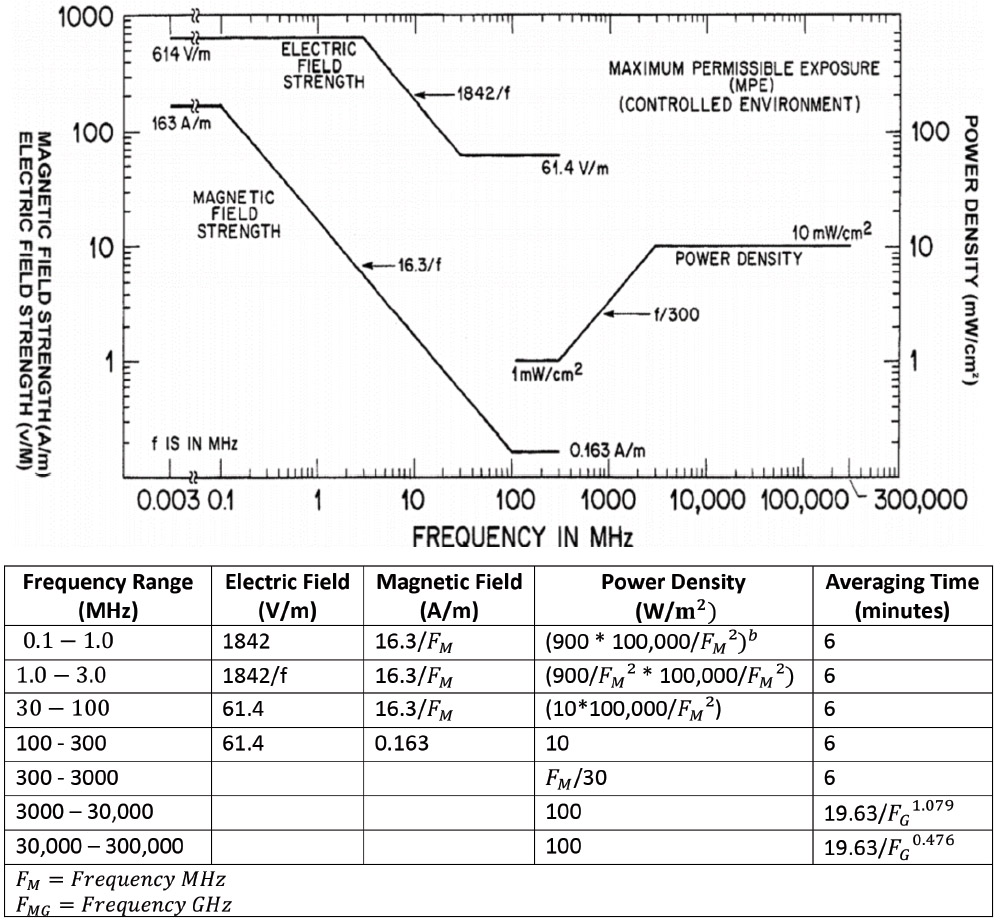
The HERP limits are established as MPE values based upon the basic restriction. The upper tier MPE limits shown in Figure 4 are presented as a function of frequency, and their values have been based upon a whole-body specific absorption rate (SAR) of 0.4 W/kg (formerly known as “controlled”). The limits were developed to control human exposures to electromagnetic energy at frequencies ranging from 0 kHz – 300 GHz, and to limit the localized SAR occurring in the feet, ankles, wrists, and hands of personnel due to exposure to such fields or contact with objects exposed to such fields. MPEs are given in terms of rms electric (E) and magnetic (H) field strengths, equivalent plane-wave free space power densities (S), flux density (B), and induced currents (I) in the body.
In addition to the main beam hazards, localized hot spots produced by reflections and resonant standing waves occurring between metal structures and buildings is also an important consideration. It is common to encounter these scenarios in areas where general power densities are initially found to be less than the maximum permissible exposure limits. Therefore, a thorough understanding of the site and the surrounding electromagnetic environment is critical.
There are several guidance documents available to assist in EMI survey planning as well as typical test methodology and measurement equipment recommendations based on the platform and type of transmitter.