
he purpose of this article is to give some history and insight into how the EMC procedures evolved at one OEM. Although other OEMs have had different paths leading to their present-day EMC specifications, they are more similar than different mostly due to the extensive reference to international standards which they have taken part in developing (e.g., EMC committees).
The EMC specifications have been developed over approximately 40 years, mostly as a compilation of actual lessons learned (some based on old issues that no longer apply) and test procedure refinement. They are all idealized simulations of the real world. Many specification setups and limits create a situation that is much worse than what would be experienced in a vehicle (could be considered as overtesting to maintain a big safety margin).
Different people looking at the same data can come up with quite different conclusions depending on their background and insight. Knowing the specification history can help EMC practitioners, especially those new to the discipline, gain insight into the implementation and the limitations of test procedures. The test evaluator should have a sense of the nature of the test and what it is trying to simulate. The goal should be to know when to “hold or fold.”
- Minimal electronics
- Mostly concerned with ignition system interference with radio and radio FCC certification.Europe more critical (long distances for AM)1977, Electronic Division dedicated EMC efforts started in electronic engine control (EEC)
- 1978-1981, a preliminary version of EMC component specifications being developed.
- 1978, EEC-1 was first-generation complex powertrain electronic system
- Initial vehicle EMC testing (no dedicated corporate EMC test facilities available at the time)
- Electronics increasing such as more complex EECsMany EMC field issuess
- Only a few dedicated EMC people
- Lots of flexibility (large EMC organizations not yet established). Test procedures could change very quickly (invention stage).
- EMC design rules being developed (vehicle and component)
- 1981, the value of PCB ground planes is realized (single most important rule)
- 1982, Electronics Division first EMC specification release (43 pages)
- 1982, Electronics Division EMC component test facility on-line
- 1982, Vehicle EMC test facility on-line
- 1983, EEC-4 was the first “clean sheet” for EMC design rules application
- The explosion of automotive electronics technology
- Design practices, test standards/procedures maturing
- Large EMC organizations and facilities in place, large inertia (makes difficult and slow to change), perspective limited (often doesn’t cross discipline boundaries).
- 1995, radio example, overcame old ingrained PCB ground myth, proved that one good ground plane much better than many
- Various specification updates led to the 1998 version where the specification was harmonized as much as possible to international standards such as ISO and CISPR
- Specifications maturing, similar throughout industry. Follow international standardsMinimal EMC field issues (if established design guidelines followed), most EMC contemporary issues are conducted immunity (e.g., microprocessor lock-up)
- New challenges – electric and autonomous vehicles
- Voice of America, Mason Ohio, 250kW curtain antenna
- American Electric Power research project, Indiana, 2.255 kV (see Figure 1)
- Port Austin Michigan Air Force radar station, 5 Megawatts (20us)
- Install different frequency 110-watt transceivers and antenna locations in a vehicle
- Vehicle electrical system EMC testing (reverse battery, load dump, etc.)Vehicle AM/FM radio interference (mostly ignition noise), FCC compliance

- TEM cell with dynamometer, 60Hz/lightning pulse, 5000v/m; 10kHz-20MHz, 200v/m max
- Anechoic chamber with dynamometer rotating table, 20MHz-18GHz, 200 v/m max


The energy coupled into a particular system is a function of much more variability than the component testing. Table 1 shows some of the differences.
It is easy to see that trying to correlate vehicle and component test results on a direct frequency and field strength basis does not make sense. Also, directionally, it can be seen that the vehicle test levels will be lower than the component test levels. The best approach is to ensure compliance under the controlled conditions of the component testing at a level high enough to ensure a high probability of vehicle success.

Here’s a brief summary of SAE and international standards (see References 1-6):
- SAE J1113, single document, 1975 version, revised in 1987, included Radiated Immunity (RI), Conducted Immunity (CI), Electrostatic Discharge (ESD), but no Radiated Emissions (RE)/ Conducted Emissions (CE).
- SAE J1113 series, 17 standards originally (most first published in the mid-1990s to early 2000s), 10 were subsequently canceled and replaced by ISO 11452 series.
- ISO 11452 series, 11 parts starting in 1995.
- ISO 7637-2 was originally published in 1984 (latest edition in 2011, new version being developed).
- ISO 16750-2, originally published in 2003 and does not cover many aspects of EMC (e.g., RI, RE/CE, many ISO 7637-2 transients). However, it does cover power line conducted immunity more comprehensively.
- CISPR 25, first published in 1995 (latest revision in 2021).
- ISO 10605, ESD, first published in 2001, latest revision in 2008 (confirmed in 2013).
Table 2 shows an overview of how the component EMC specification has changed over the years. It can be broken down into two periods. Before the year 2000, many new concepts were tried, such as:
- Development of many new test methods (e.g., stripline, tri-plate)
- Development of realistic load dump simulator although not used in later specifications
- RI/RE acceptance criteria quantified deviations although not included in later specifications
- Later 1990s, as can be seen in the brief summary above, standards were first becoming common.
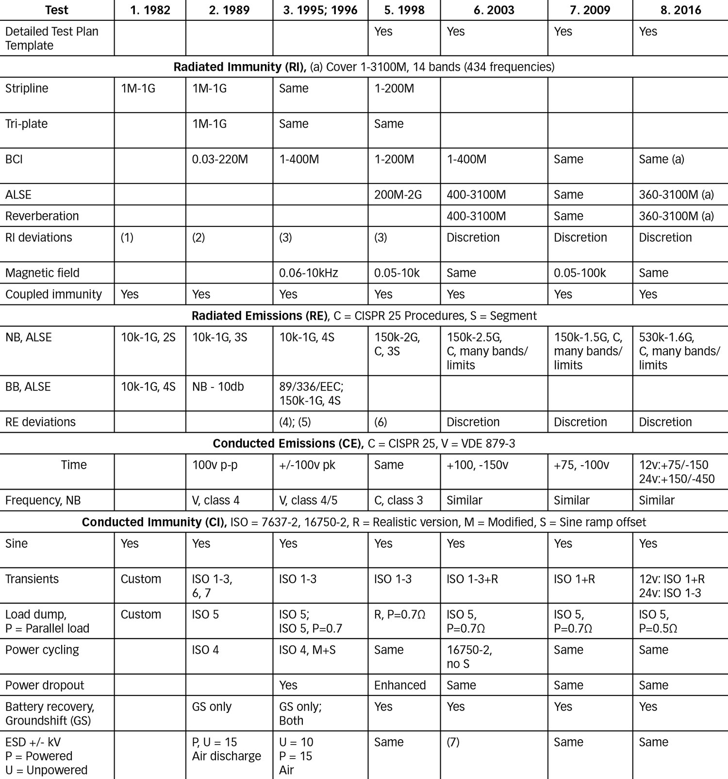
Table 2 Notes:
- Minor malfunctions at 200v/m if OK at 150v/m
- OK at 50 or 75 % of limit (many caveats). See RI Acceptance Criteria section, option 1.
- Must comply over 90% of any 100MHz span and must comply at 50% of limit (many caveats). See RI Acceptance Criteria section, option 2.
- Z = (statistical limit – average) / standard deviation. See RE Acceptance Criteria section.
- SCFM = SCFM = (∑ Xi 2) 1/2 (N/Span). See RE Acceptance Criteria section.
- PSD = ∑ (X / L) 2 / (Frequency Span / Resolution). See RE Acceptance Criteria section.
- ESD = U, contact = 4, 6; U, air = 8; P, contact = 4, 6, 8; P, air = 4, 6, 8,15, 25 (some applications)
- RI: Stripline and tri-plate dropped, reverberation method added (preferred), small antenna over the device under test (DUT) to address cell phones, 14 bands (434 discrete frequencies), deviations subjective
- RE: Many specific bands and limits (was three or four continuous segments), deviations subjective
- CE: New test for low voltage (< 60v) current
- CI: Realistic transients implemented (ref 14), load dump changed to ISO pulse 5 with 0.7/0.5 Ω in parallel with the DUT
- ESD much more refined
- Many tests are idealized versions of the actual event, only an approximation to the real vehicle. They are good at comparing different components.
- Some malfunctions only occur when the stress (e.g., transient) lines up with a certain point in software execution.
- Impractical to test at different temperatures, components such as electrolytic capacitors can change dramatically over temperature.
- Impractical to test some products in all their modes of operation.
- Impractical to monitor all possible functions in detail.
- Impractical to test all subsystem component interactions. Often, EMC testing is the first time a DUT is setup up in a subsystem configuration.
- Analysis, focus on contemporary issues.
- Verify EMC design guidelines implementation.
- Early development testing using internal company EMC facilities.
- If these facilities are not readily available, use low-cost methods (see Reference 7 example).
- Failures are good (early in the design process) – information theory, maximize information.
- Limited time on each project, must keep on schedule.
- Must address many other design and manufacturing aspects.
- Keep costs down (weigh cost/benefit) and make a profit.

Stripline (Reference ISO 11452-5): Actually, this is a microstrip but the name stripline somehow stuck. It was the first method for exposing DUT and harness wiring to RF energy with a fairly uniform field over a wide frequency range. Since many RI concerns are due to harness pickup, a stripline is good at recreating actual vehicle concerns. However, it has a limited test volume and cannot expose larger DUTs. This shortcoming was first illustrated by instrument clusters. Pre-production testing at the vehicle level showed immunity concerns (switching power supply malfunction caused damage) but the stripline did not show this effect. The tri-plate line overcame this limitation and recreated the concern by providing more test volume to insert the cluster itself within the test volume.
Tri-plate line (TPL) (Reference SAE J1113-25): The term tri-plate line (TPL) was coined by Myron Crawford who invented the TEM cell. The TPL is basically an open-sided TEM cell that has a uniform field to a higher frequency than the TEM cell since it avoids the resonances inherent in a closed structure like a TEM cell. In addition, the TPL configuration allows a wider plate separation (more test volume) and narrower width than a stripline while maintaining a reasonable impedance (70Ω). The narrower TPL width for a given plate separation translates into a higher frequency cutoff since the cutoff frequency is inversely proportional to the width. The TPL also provides a more uniform field than a stripline since the field is more contained within its volume.
Bulk current injection (BCI) (Reference ISO 11452‑4): Bulk current injection (BCI) was developed in Europe as an outcome of the Falklands war (e.g., H.M.S. Sheffield’s sank due to EMC issue) and its use rapidly spread because it is relatively inexpensive and easy to set up. It also does not require a lot of power (RF power amps are expensive).
Absorber lined chamber (ALSE) (Reference ISO 11452‑2) and Reverberation chamber (Reference IEC 61000-4-21): An excellent paper that compares these two methods (Reference 8) shows there are differences in the test results between the two. However, the reverberation method is preferred since it is faster, requires less power, and provides more complete illumination of the DUT and wiring harness without the need for multiple DUT orientations and antenna polarizations.Either method will show immunity concerns.
Magnetic field: This test was developed to represent the magnetic fields set up by high current loads to which certain devices (e.g., Hall sensors) are sensitive.
Coupled Immunity, Ignition: This test simulates crosstalk (from mutual capacitance and inductance) to DUT wiring caused by secondary ignition wires. This test was deleted in newer specifications since vehicles no longer use such ignition wires.
Coupled Immunity, Transients: This test also simulates crosstalk to DUT wiring caused by other noisy wires in the same wiring bundle. The noise sources are mostly from inductive loads being mechanically switched (solenoids, motors, etc.). The waveforms are very complex and have fast rise/fall times that efficiently couple. The coupled noise has such high-frequency components and low energy that normal filtering in the DUT is usually sufficient to mitigate any concerns with this. However, some circuits cannot have much filtering, or it will affect the normal signal and may require special measures such as shielding.
For the simulator, the waveforms are best duplicated with an actual inductive load being mechanically switched. The chattering relay as described in the following section on transients is an excellent source of noise. In an actual vehicle, these transients are usually single events and very random in amplitude and duration. If these single event transients were attempted for this test, the time involved to detect a possible malfunction would be excessively long. Therefore, the noise created by this test provides a continuous series of random transients for ease of detecting a malfunction.
These examples of acceptance criteria options provide minimal risk and allow some degree of flexibility in evaluating test results while ensuring that the device meets the intended design requirements. It has been empirically determined over many years of comparing component level and vehicle level test results. In addition, the specification limit already includes a big safety margin.
Also, this is just one EMC test among many. If a module passes RI with these acceptance options in addition to all the other RF tests which indirectly give an indication of RI (e.g., RE, ESD, etc.), it is highly likely to meet the intent.
Option 1: During this time frame (the late 1980s), there were limited communication bands to worry about:
- Deviations allowed at 50% of the limit, and the frequency range over which the deviation occurs is < 5MHz. No more than three of these may occur (no more than one in a given radio communication band).
- Deviations allowed at 75% of the limit, and the frequency range over which the deviation occurs is < 5MHz. No more than five of these may occur (no more than one in a given radio communication band).
- Comply with all functional performance status requirements (i.e., I, II, III, IV) over a minimum of 90% of any 100 MHz span (sliding window).
- It may degrade no more than one functional status classification over the remaining portion of that span.
- Furthermore, it must comply with its intended functional class when tested at 50% of the specified limit.
There are many papers that evaluate the setups for RE (similar concepts would also apply to RI) which show how the setup is not truly representative of the actual vehicle, and differences between test labs can be high (References 9 and 10). This gets to the degree of flexibility addressed in the acceptance criteria sections later in this article.
Present-day RE limits are very complex. Having a lot of bands/limits is not realistic since it is only good for the specific component test configuration. Levels will be amplified or attenuated differently in the vehicle. It’s more important to control the total energy emitted.
It is very difficult if not unpractical to get the same results at each frequency from different test labs for radiated emissions due to the many variables involved. However, it is possible to establish a correlation between different testing laboratories on a statistical basis. Some technical papers (References 11 and 12) have suggested a solution. For example, if only the highest emission levels are compared independent of the emission frequencies, a higher degree of correlation is possible. Such an approach may be justified under the assumption that the test facility design does not significantly affect the total emissions power but mainly leads to the radiated power spectrum redistribution.
The simplistic approach of being below a limit line can result in chasing a red herring and overdesign, needlessly increasing the cost. For example, even if the RE is consistently below a limit line, it is more probable that a real-world concern would exist if there were many spectral lines close to and under the limit (i.e., the spectral density would be high). Another situation would be to fail a module that only had a few data points slightly over the limit but otherwise showed little emissions.
There are many differences between the module test setup and the vehicle configuration (see Table 1) and it is unlikely that there is a one-to-one correlation between the testing laboratory and the vehicle (at each frequency). For example, even if a module was below a limit line using the bench test configuration, there would be an entirely different configuration in the vehicle so that those frequencies that were below the limit line are now connected to a system that more effectively radiates, resulting in customer concerns.
Newer versions of the specifications have some discretion as to what passes, but the ultimate decision is subjective and depends on who is looking at the data. With that in mind, consider using a limit line (not applicable to legal requirements) as only one part of a decision for acceptance.
Z score: This was included in the 1995 spec version. If emissions are above the limit, apply a statistical limit 5dB above the preferred spec limit. Within each antenna range, compute the average, standard deviation, and resulting Z score. Z shall be > 1.3. Use linear values (not log).
Span = Frequency span
PSD: Another option that was included in early versions of the component specification was radiated emissions narrowband data analysis – power spectral density (PSD), (Reference 13). An important parameter to consider is the total amount of power available to excite the vehicle wiring – PSD addresses this concept.
The PSD was automated for a time, just to see if the concept works. Basically, it is the same as an EMC expert looking at it and saying it is OK or not. Figure 4 shows an example. All of these emissions change around with harness lengths so you’re just looking for how much energy is there. It’s energy because you square the voltage and divided by a certain bandwidth. With a little experience, you learn what is good or not. When this concept was presented to the EMC community (SAE J2556), I thought it would be accepted as a more reasonable approach. However, it never caught on for the same reasons stated in the RI Acceptance Criteria section.

Frequency Domain: This test addresses controlling continuous or long-duration emissions on power leads (e.g., commutator brush noise, pulse width modulation). Early specification versions used VDE 0879-3 procedures and limits. All subsequent versions (starting in 1998) use CISPR 25. The purpose of this test is similar to that of the radiated emissions test. However, in the radiated emissions test, the wires are bundled together which may give a radiation canceling effect due to the flow of current in adjacent wires in opposite directions. This test addresses systems that draw current through large loop areas (e.g., power feed from fuse panel and ground through sheet metal) where this canceling may not occur.
The two relevant international standards are ISO 7637-2 and 16750-2. ISO 7637-2, originally published in 1984, had many pulses/waveforms (1-7) but have been reduced to only pulses 1-3 (2004), Pulse 4 (power cycle) and Pulse 5 (load dump) now reside in 16750-2, Pulses 6 and 7 were outdated and deleted.
A more representative version of vehicle transients is given in newer versions of the EMC specification (starting in 2003). Reference 14 gives a detailed analysis.
A key element of these newer, more realistic transients is the chattering relay. The chattering relay test simulates these transients and interruptions by configuring a single relay in a unique fashion. The configuration consists of placing the normally closed (NC) set of contacts for the relay in series with the DUT power input. Figure 5 shows a simplified example where selectively closing SW1-4 can achieve different types of dropouts and transients.

The actual test condition with the DUT in the circuit is set under similar conditions except that a load is placed in parallel with the DUT (0.7 represents the minimum vehicle electrical loading such as fuel pump and engine control, 14 v / 20 amps).
This test is among the most severe tests and potentially destructive and gets a lot of attention since it often involves adding cost. However, analysis has shown that ISO Pulse 5 load dump simulators were not realistic and could result in overdesign. An important parameter that must be duplicated in a realistic simulator is the action integral (integral of I2 dt) imparted to the DUT. This is the parameter that causes damage to many devices. Tests were conducted comparing the results of three different methods of subjecting a Metal Oxide Varistor (MOV) to a load dump, as follows:
- A commercial simulator, ISO pulse 5, 38 A2 sec, which resulted in permanent damage.
- Actual alternator is driven by electric motor as mentioned above, 8 A2 sec, which resulted in no damage.
- Custom-designed electronic simulator based on 2. above, 10 A2 sec, which resulted in no damage.
Even though all three tests transfer approximately the same Joule energy to the DUT, the commercial simulator had a much higher action integral, and the custom electronic version is much closer to the actual electromechanical (alternator) version. Recent versions of the EMC specification have reverted to the use of the ISO 7637-2 Pulse 5 (now resides in ISO 16750-2) due to its wide use in the industry. However, adding a parallel load (e.g., 0.5 Ω) absorbs most of the energy.
It should be noted that the actual load dump waveform (without loading) is much more complex than the waveforms created by these electronic simulators. The real event consists of an arcing period of about 50us to 10ms followed by a positive spike up to 200 volts of about 50 – 100us. After this spike, the alternator voltage decays according to the field coil circuit time constant. During this decay, high alternator ripple is superimposed on the waveform.
For this test, the test setup should retain a low impedance. The sinewave portion of the power cycle is meant to represent engine cranking, in which the exhaust and compression cycles present a varying load on the starter motor and result in the sine voltage. Early versions of the specification also had this sine portion offset ramping, which was deleted in later versions to align with international standards. This offset is important since it was derived from field concerns. It’s important not to simplify the waveform with a square wave; the sine is more realistic, and using a square wave will not detect concerns related to circuits that are sensitive to hysteresis (e.g., voltage detecting).
This test also addresses switch bounce and intermittent connections. The real-world waveforms due to these events are very random in nature. One of the mechanisms for intermittent connections is due to connector pin corrosion buildup over time (fretting), a common finding in older vehicles with inexpensive, open connectors. If the pins/wires in the connector shell are not rigidly retained and sealed, the connection can be momentarily broken when the vehicle hits a bump on the road.
For all power dropout tests, the test setup should duplicate the open circuit condition. This is done by inserting a series diode with the simulator. In addition, a resistance is placed across the DUT to represent other vehicle loads between the DUT and the intermittent connection. This resistance bleedsoff the input capacitor charge, as would be the case in the vehicle.
In earlier versions of the specification, the noise was injected via the secondary of a transformer. However, this created problems for modules that drew higher currents since the transformer secondary had an impedance of 0.5 ohms. Recent versions of the specification use a low impedance power amplifier.
- For all ESD testing, the placement/orientation of the DUT with respect to the ground plane is critical. The amount of charge that is transferred to the PCB is proportional to the ratio of the capacitance of the PCB (with respect to the test ground plane – i.e., stray capacitance) to the capacitance of the ESD simulator. Also, the ESD current paths depend on the orientation of the DUT. To illustrate this, for the unpowered handling test, when modules are placed perpendicular to the ground plane with the connector up, they may be damaged by the ESD currents flowing the length of the PCB from the connector pins to the ground plane. This is unrealistic and results in failures that do not occur in the field.
- The routing of the ESD gun ground strap is critical for repeatability since it radiates. Connect ESD gun ground strap (inductance < 1.5 microhenries) to the ground plane. It should be routed as far as possible from the DUT.
- The simulator probe should be perpendicular to the test point (+/- 15 degrees). The probe tip should be slowly (approximately 1 cm/sec) moved towards the test point until a discharge is obtained. Variations in the speed of approach can lead to a variation in the rising slope of the current waveform (amps/nanosecond) by a factor of 20 or more. Therefore, a fixture to control the approach speed and angle is advisable to ensure the best repeatability.
- Completely different DUT responses can occur at different ESD voltage levels. Low-voltage and high-voltage ESD pulses uncover more concerns than medium-voltage pulses. At lower voltages, the rise times are faster and peak currents higher (less corona bleed-off). At high-voltages, a series of multiple discharges can occur. The ESD multiple discharge phenomenon is characterized by successive pulses, each possessing lower energy levels than the previous pulse. Subsequent pulses can be separated by a time period ranging from 10 us to 200 ms. For medium-voltage ESD pulses, multiple discharges are less likely, and the associated corona predischarge will slow down the rise time while limiting the peak current.
- Pins/terminals should be discharged between ESD discharges via a 1 Megohm resistor to prevent cumulative voltage buildup.
- Use an ESD static meter to verify that a charge buildup is not occurring between ESD discharges. Such a buildup will make subsequent discharges non-realistic since the ESD gun and the DUT will be at similar charge levels, thereby preventing a discharge. If charge buildup is present (usually the case for DUT with nonconductive housing), use an air ionize to neutralize the charge.
- In-house-built ESD simulators are not acceptable since construction is very critical. In addition, guns from different vendors are not the same. Studies have shown that, even though the voltage waveform is similar when tested into a standardized termination, there are other events occurring, such as the radiated fields, which vary from one simulator to another. In fact, these emissions can vary with different simulator orientations with respect to the DUT.
- The voltage and power threat for an IC mounted on a PCB can be much worse than an IC by itself. The voltage rating of an IC is often confused with the module ESD test level. The ESD rating for an IC is under completely different test conditions (e.g., direct discharge to each pin, not air discharge). It is not possible to establish any meaningful relationship between individual ESD immunity levels of ICs, and the ESD immunity level of a PCB as a whole.
Some options worth considering to address test cost and efficiency include:
- Follow the approach for analyzing data presented earlier in this article to avoid over-testing (see RI, RE acceptance criteria).
- Another option that may have some appeal is to use a generic specification, allowing some minor differences unique to an individual OEM. Present specifications are already somewhat generic since they heavily reference international standards. Some generic examples are:
- A generic automotive (Tier1) EMC test standard, http://www.tridatacom.co.uk/Downloads/Papers/Papers/AutoEMC2006.pdf
- ZVEI (German Electrical and Electronic Manufacturers Association) Generic IC EMC Test Specification, May 2017
- Since present-day OEM specifications are very similar, another option is that one OEM could accept another OEM’s test results, at least in part, if some criteria are met and are verified at an accredited EMC lab.
- Module supplier proposing an EMC specification. Since some suppliers deal with many OEMs, they may have a wider, more cost-effective perspective.
- For some products that meet certain requirements (such as following established EMC design practices, a mature product design with a good track history, or current compliance with similar specifications), only some of the tests may be required.
- SAE J1113 Series, Electromagnetic Compatibility Measurement Procedures and Limits for Components of Vehicles, Boats (up to 15 m), and Machines (Except Aircraft) (16.6 Hz to 18 GHz), 17 parts originally.
- ISO 11452 Series, Road vehicles – Component test methods for electrical disturbances from narrowband radiated electromagnetic energy, 11 parts
- ISO 16750-2, Road Vehicles – Environmental conditions and testing for electrical and electronic equipment – Part 2: Electrical loads.
- ISO 7637-2, Electrical disturbances from conduction and coupling – Part 2: Electrical transient conduction along supply lines only.
- CISPR 25, Limits and methods of measurements of radio disturbance characteristics for the protection of receivers used on board vehicles.
- ISO 10605, Road Vehicles – Test methods for electrical disturbances from electrostatic discharge.
- Application of Thrifty Test Equipment for EMC Testing, In Compliance, December 2021.
- Achieving Correlation of Radiated RF Immunity Testing Performed in an Absorber Lined Shielded Enclosure and a Mode Tuned Reverberation Chamber, Craig W. Fanning, 2006 IEEE EMC Symposium.
- A Design Review of the Automotive Radiated Emissions Test Fixture, Tom Mullineaux, Interference Technology, 2014.
- Investigation of the Calibration Procedures from CISPR 25, Annex B, for Use with Vehicle Component Testing, Dennis Swanson, 1998 IEEE EMC Symposium.
- Statistical EMC: A New Dimension in EMC of Digital Electronic Systems, Anatoly Tsaliovich, AT&T, 1987 IEEE EMC Symposium.
- Qualification of Radiated EMI Test Sites Using Statistical Methods, Joseph DeMarinis, 1992 IEEE EMC Symposium.
- SAE J2556, Radiated Emissions (RE) Narrowband Data Analysis – Power Spectral Density (PSD).
- Comparison of ISO 7637 Transient Waveforms to Real World Automotive Transient Phenomena, Frazier, Alles, 2005 IEEE EMC Symposium.
