
ost electromagnetic interferences (EMIs) in the field are conducted emissions/immunities, radiated emissions/immunities, electric fast transients (EFT), and electrostatic discharge (ESD). There are, however, other types of EM-related disturbances, including low-frequency magnetic fields, the subject of this article.
The power-frequency (50-60 Hz) magnetic field is a direct result of currents flowing in power networks. When low-frequency currents flow in the entire power network, depending on the size of the current-circulating loop, the impact on equipment/products in the environment can be significant. A typical case is an equipment with a cathode ray tube (CRT) screen. The display on a CRT screen would appear to wobble due to the presence of a nearby low-frequency field1. Professional audio equipment such as electric guitars, tape recorders, and loudspeakers are also sensitive to external magnetic fields. EN 61000-4-8 defines the test method for basic power-frequency magnetic fields2.
In recent years, many low-frequency magnetic field issues have been identified in new product applications, such as products using electron-beam technology and electric vehicles (EVs). Products such as additive manufacturing equipment using electron-beam technology are also sensitive to power-frequency magnetic fields and poor immunity could lead to inaccuracy in the manufacturing process. In the case of EVs, traction motors generate fluctuating currents up to 2 – 3 kHz, and wireless power transfer (WPT) systems for battery charging are operated at about 85 kHz3.
The issue with low-frequency magnetic fields in this case is often related to health and safety. The International Commission on Non-Ionizing Radiation Protection (ICNIRP) Guidelines 20204 describes the potential health and safety impacts of human exposure to electromagnetic fields. According to the Guidelines, the main physiological effects of electromagnetic field exposure include the electro-stimulation of the nervous system, resulting from electric fields being induced in biological tissues under exposure to time-varying magnetic fields with frequencies up to 10 MHz.

In this article, the discussion of low-frequency magnetic fields is based on applications where the frequency range is below 500kHz. The low-frequency magnetic field challenges in EV applications are discussed. Low-frequency electric fields and plane waves are outside the scope of this article, as are low-frequency magnetic fields produced during the EV charging process.
First, some basic theory about low-frequency magnetic fields is in order.
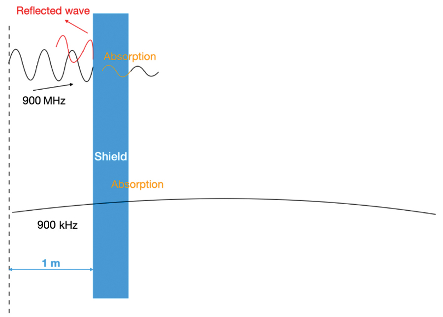
As shown in Figure 1, the laws of physics dictate that the wavelength is large when the frequency is low (900 kHz), hence the same distance becomes near field for lower frequency noise. In this case, the shield cannot provide sufficient reflection loss. The absorption loss is also reduced and is at a low-frequency. As a result, low-frequency magnetic field shielding can only be achieved by the following techniques:
- Using thick conductive metal material such as steel, which often works well, but the drawback is the weight. Aluminium or magnesium are much lighter than steel, but they have insufficient low-frequency shielding properties and, therefore, cannot be used in this application.
- Using a magnetic material such as mu-metal to increase the absorption loss. However, this technique doesn’t work for low-frequency electric fields or plane waves (see Endnote #5). Another drawback of magnetic materials is that their permeability decreases with frequency.
- Active shielding techniques to cancel out the low-frequency field6, which works in applications where the product suffered from power-frequency (50‑60 Hz) magnetic fields and is not constrained by size.
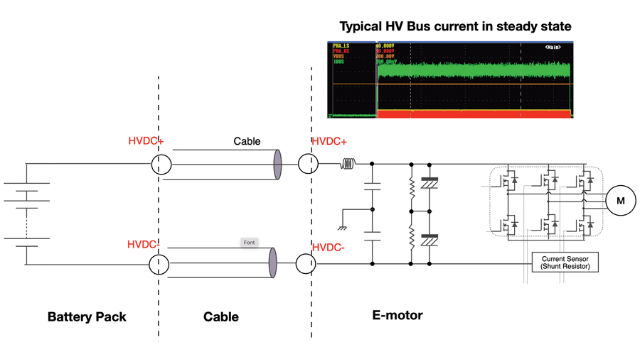
A simplified system diagram is shown in Figure 2. Often there is a high-voltage (HV) junction box between the HV battery pack and other HV loads. For demonstration purposes, the junction box and other HV loads are not shown.
When the traction motor is in motoring mode (that is, when the motor is in cruising mode), currents are drawn from the battery pack. The currents can reach a much higher level when the vehicle accelerates as the motor demands more power. When an EV is in braking mode, the motor starts regeneration and large amounts of currents are fed back to the battery pack. In this case, the HV wiring and harnessing determine the current-circulating loop area. Hence, the low-frequency magnetic field depends on the motor speed, the motor drive switching frequency, its operating mode, and the impedance of the cables.
The HV bus bar currents consist of many frequency contentsHere is the frequency contents breakdown:
- From 1 Hz to a few kHz, static magnetic field noise is often generated by the battery pack and DC bus bar current flow.
- In the frequency range of a few kHz, noise is generated by the electric frequency of a rotor, which depends on the mechanical speed and the number of poles of the rotor.
- From tens of kHz to a few hundred kHz, noise is generated by the switching frequency of the motor drive.
- The sharp rise time of the motor drive generates noise in the high-frequency range between a few MHz and a few hundred MHz.
- Partial discharge of HV cables and bearing currents of the traction motor generate noise beyond hundreds of MHz.
- The battery pack, HV cable, and the traction motor forms a C-L-C circuit; resonances could occurdepending on the geometry of the structure.
Test standards are being developed to test against low-frequency magnetic fields. The aim of these tests is to place a limit on the magnitude of the electromagnetic fields generated by a unit to ensure that compliance to the human exposure reference limits detailed in ICNIRP Guidelines can be achieved during vehicle level testing. Unless specified in the approved test plan, testing is often performed in the frequency range from 1Hz to 500 kHz using a 100 cm2 three-axis sensor, though there can be proximity errors in the test set-up7.
Considered as a cost-effective solution, this approach also has the benefit of being mechanically strong, which is great from the battery pack safety point of view. It does, however, have the disadvantage of being heavy, which could be a big drawback for an EV application. One of the pain points of modern EVs is their limited mileage, which could be extended significantly when the weight of the vehicle is reduced.
A similar application is electric aircrafts where weight is even more important. Currently, the solution there is to use aluminium material for the battery pack. But even aluminium material is considered heavy, so carbon fibre composite material is preferred. Layers of copper sheeting need to be added for shielding and to protect against lightning strikes.
Because of the limited options to shield low-frequency magnetic fields effectively, a better approach is to control the magnetic fields at their source, and avoid or minimize generating them8.
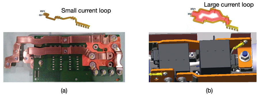
Magnetic fields depend on the loop size and the current level. Since the current level cannot be reduced, efforts should be made to reduce the loop size. Reducing loop size for low-frequency magnetic fields mainly involves:
- Planning battery housing, which includes battery cells module layout, battery management system (BMS) wiring layout, and battery bus bar layout. The good news here is that safety, thermal, and system efficiency requirements all require an optimized wiring structure.
- HV junction boxes also need to adopt smaller/improved conductor rail designs. This is often an area that can be overlooked by design engineers. A typical case is that bus bar/wiring can be separated by the larger contactors. In Figure 4, two examples are shown to demonstrate the point.
- Optimizing the wiring and harnessing in the HV power network. An optimized system is often achieved by integrating multiple modules.
Reducing the magnetic field loop size and using advanced materials should be considered in the vehicle design stage. Due to its superior attenuation at very low frequencies (<10 kHz), steel might still be a preferred choice for vehicle manufacturers. Integration of power modules should also reduce the risk of emitting low-frequency magnetic fields. Active shielding may be used for such applications but require further study.
- K. Armstrong, “A Practical Guide for EN 61000-4-8 Power-frequency magnetic field immunity test,” REO UK LTD.
- EN 61000-4-8:2010 Electromagnetic Compatibility (EMC) – Testing and Measurement techniques. Power frequency magnetic field immunity test, 2010.
- A. R. Ruddle, “Proximity Errors in Quasistatic Magnetic Field Measurements on Line Sources Using Coil Probes,” Proceedings of the 2019 International Symposium on Electromagnetic Compatiblity, Barcelona, 2019.
- ICNIRP, “ICNIRP Guidelines for limiting exposure to electromagnetic fields (100kHz to 300 GHz),” Health Physics, Vol. 118, Issue 5, p. 483-524, 2020.
- H. W. Ott, Electromagnetic Compatibility Engineering, New Jersey: Wiley, 2009.
- Aldo Canova, Juan Carlos de-Pino-López, Luca Giaccone and Michele Manca, “Active Shielding System for ELF Magnetic Fields,” IEEE Transactions on Magnetics, Vol. 51, No. 3, 2015.
- See Endnote #3.
- See Endnote #5.