
oday’s communication, transportation, and power delivery systems all depend on the extensive use of batteries to keep them functioning in a safe and reliable manner. Battery cell technology has its origins in the late 1700s, while fuel cells were not available commercially until the mid‑20th century. But today’s batteries and fuel cells are an amazing combination of the application of principles of chemistry and electrical engineering.
The standard approach today is that when a battery is the only power source of an electrical system (referred to as the primary power source), analysis techniques are normally applied to characterize the battery as being able to supply constant input voltage to its load. As we have all experienced in our daily lives, constant input voltage conditions do not really exist unless there is an additional power source to maintain the battery’s state of charge.
Unfortunately, this results in a potential divergence of the expected results of electrical and electronic system performance when using the theoretical model compared to what may be experienced in actual real-world applications. For example, when an electrical motor is tested at a constant input voltage, the performance of that motor will vary if the input voltage is changed.
To help engineers better replicate these conditions, this article describes the methods that can be used to increase the correlation of the testing of battery and fuel-cell-powered systems with their actual applications.
There are many benefits of having up-front test data that has a high correlation to a system’s actual performance. These new methods can be based on the fundamental principles of the conservation of energy when a battery is used as a system’s primary power source. It turns out that, instead of a battery having an unchanging constant energy delivery rate (with a constant current and voltage depending only on the load’s power demand), a battery’s behavior will be impacted due to the type of load to which it is supplying energy, which will then change the characteristics of a battery’s discharge conditions.
There are two types of electrical loads, passive and non-passive. If a load is a passive load, there is no power required. A non-passive load is an electro‑mechanical load like a motor connected to a pump or fan. The pump or fan has power that is required from the mechanical domain, and the motor must provide the required mechanical power. The mechanical power must come from the electrical domain. Note the electro-mechanical coupling could be direct or indirect LCA as an applicable methodology.
When a battery is delivering energy to non-passive loads, the power demand must be satisfied, such as with a motor driving a pump. With this insight, battery modeling can be designed to also provide test results that have a higher correlation with other types of electrical components, such as common power electronics, such as capacitors and inductors.
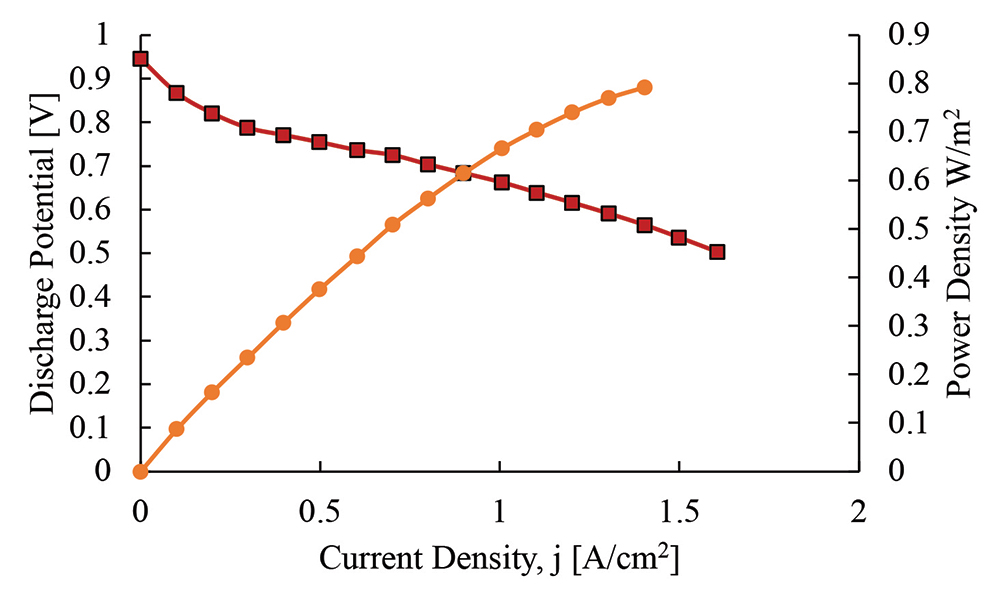
Both batteries and fuel cells are electro-chemical systems, but a battery is an energy storage device, while a fuel cell is an on-demand power supply that provides power as long as the fuel cell is supplied with hydrogen and oxygen. The fuel cell is considered a current-controlled voltage source (CCVS) and its output voltage is a function of its output current.
As a result, batteries and fuel cells are electro-chemical components that convert chemical energy into electricity and heat. Their energy is stored chemically, and their characteristics will be different from other electrical energy storage devices.
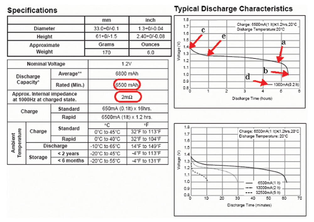
Based on the behavior shown in Figure 1, a battery is sometimes believed to have an unchanging effective resistance. However, the battery discharge voltage will change based on its state of charge as well as the current it is delivering. The consequence is that, as energy is extracted from a battery, the amount of stored charge in the battery decreases.
The SIMULINK model in Figure 2 shows a battery model that correlates discharge voltage, current, resistance, and the battery’s state of charge (SOC).
What the model in Figure 2 (with the coefficients that have been obtained from experimental data) shows is that a generic battery model can be used that will incorporate the ability to determine the battery charge, as well as the computation of discharge voltage and resistance.


This information then gives us the ability to create a generic battery model that is dependent on certain points in the discharge curve, as shown in Figure 4. The points can be used to determine varying battery SOC and will then yield a quantifiable battery discharge function.

Since a battery is a component that stores its energy chemically, it can have two types of discharge characteristics, either constant current or constant power. In Figure 5, we see that, during constant current discharge, the battery discharge voltage is also continuously decreasing. As a result, the power delivered by the battery will also decrease due to the falling voltage.
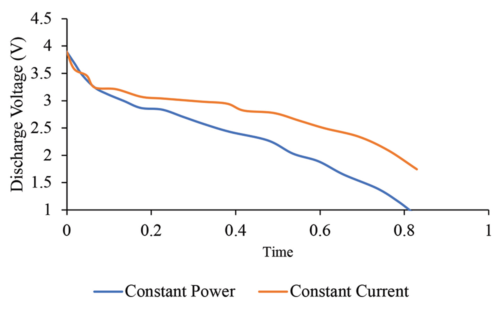
In constant current discharge, the discharge voltage decreases along with the SOC. If the electrical is passive, then it can accept a constant current discharge. However, if the load is non-passive, it will require constant power discharge.
In Figure 6, we see how the battery discharge current is influenced by constant current and constant power discharge.
During constant current discharge, the current remains constant and does not change with time. In the case of constant power discharge, the current is low initially when the voltage is high and the current increases as the battery discharge voltage decreases to maintain the power. Note that during constant power, the power discharge is constant at the expense of decreasing voltage and increasing current. Also, the capacity of the battery will decrease more rapidly during constant power discharge and must be sustained by integrating the current.

Unlike a fuel cell that is capable of providing a constant voltage and current, a battery is limited in that it can provide constant power but not constant voltage.

This theory can also be applied to a DC motor and a resistor, inductor, and capacitor (RLC) circuit. The circuit model of the DC motor is shown in Figure 8.


The last term of the equation contains power and current. The required power is known, but current and voltage are changing. Therefore, we cannot solve the equation for voltage and current at the same time. First, we must solve for the current. Then, we can solve for the voltage.
To further complicate the issue, the efficiency of electronics changes with input voltage is shown in Figure 9 and Figure 10.


Equation 5 and Equations 1 and 2 are not the same, but Equation 5 can be simplified by using Equations 1 and 2 and assuming a constant voltage. In the case of Equation 5, LCA cannot be used. But the insights derived by the current in the denominator can help explain inrush current.
The new equation is non-linear and non-homogenous and would give a different solution to the existing model.


It can be seen that LCA is a special case of the conservation of energy.
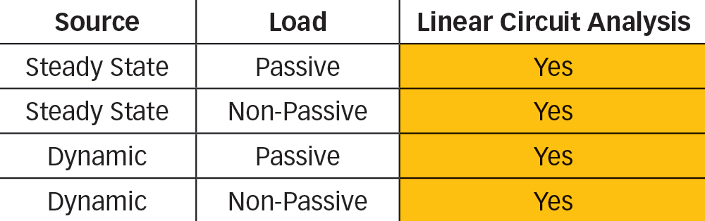
The next step involves examining where we are with our current circuit analysis, as shown in Figure 11. Based on our dynamic motor modeling with a battery as the main power source, we are proposing adding an additional tool to the toolbox and limiting the use case of LCA. The new proposed matrix is shown in Figure 12.
Like the battery, the other source of electro-chemical energy is the fuel cell. Unlike a battery, a fuel cell is an open system in which hydrogen and oxygen are delivered to produce voltage and current. The next question that comes up is where the fuel cell fits within the electrical matrix and whether it will follow the battery or go elsewhere.

Note that the voltage drops as more current is drawn, but the system can reach a steady-state solution. In this case, Equation 4 can be solved since the power source is considered a current-controlled voltage source:

The first case that is examined is the capacitor. The electrical power is computed by the voltage and current, as shown in Equation 12:


The last component is the inductor, and the voltage and current relationship for this component is shown in Equation 17:


A non-passive load involves loads in which power requirements must be satisfied, and the voltage and current respond to the power needs. Power is known in the case of electrically generated power. But voltage and current are not known in cases in which the battery is the primary load.
If KVL is applied, the power is divided by the current to convert into the voltage domain, as shown in Equation 19:

The proposal for electrical circuit analysis involves the transition from the matrix shown in Figure 11 to the matrix shown in Figure 12. To proceed, the load and the source need to be examined to determine whether linear circuit analysis is applicable. For instance, in a case where the source can provide a constant voltage and current, such as with a fuel cell or a power supply, the input voltage to the system will be constant. In this case, we can solve for the voltage and current at the same time and LCA can be used.
The next step of the process involves examining the sources to see how they will impact the proposed electrical matrix. In addition, all four cases will be tested to validate the theory.
The raw form of the conservation of energy can use LCA when passive elements are present. But there are limits to the use of LCA, and a new tool is needed to solve new problems. Our hope is that new insights resulting from our research will help size batteries for existing needs, size electronics components to minimize conduction and switching losses, and improve electronic efficiency.
In addition, battery evaluation needs to include the connection between the source and the load. For instance, a motor used in a battery electric vehicle should be tested with a variable input versus a constant input load to get an accurate representation of how the motor and electronics will actually behave in the real world.
- Handbook of Batteries, Third Edition, David Linden, Thomas Reddy.
- https://www.mathworks.com/help/sps/powersys/ref/battery.html
- https://ctms.engin.umich.edu/CTMS/index.php?example=MotorSpeed§ion=SystemModeling
- https://www.ti.com/lit/ds/symlink/tps61045.pdf
- Fuel Cell Fundamentals, Second Edition, Ryan O’Hayre, Suk Won Cha, Whitney Colella, Fritz B. Prinz.