Editor’s Note: The paper on which this article is based was originally presented at the 2020 IEEE International Symposium on Product Safety Engineering held virtually in November 2020. It is reprinted here with the gracious permission of the IEEE. Copyright 2021 IEEE.
Depending on the technical discipline, patterns created by the flow of electrical current have been referred to as dendrites, water trees, or fern patterns—the general term is Lichtenberg figures [1]. The terms dendrite and water tree are generally applied to dielectric failures [2], while the term fern patterns have been applied to patterns sometimes formed in epidermis from a lightning strike. The term fulgurite [3] refers to patterns of fused silica formed from a lightning strike to a soil or sand surface.
Dielectric breakdown of the ethylene propylene rubber (EPR) insulation of electrical power transmission cables has been variously described in the literature as water trees and dendrites. The pattern of formation was first realistically modeled in 1984 and referred to as the dielectric breakdown model [5]. Dendrite patterns can form in circuit assemblies by the stress of an electric field [2] and in electrical insulators (dielectrics) from electric field stresses [5].
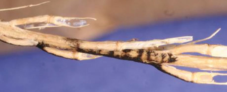
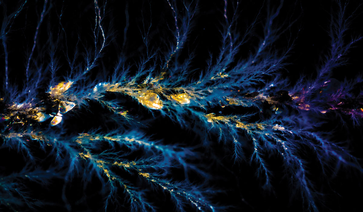
Apparently undocumented in the literature (modern art notwithstanding) is that the flow of electric current can cause Lichtenberg figures in plants (Figure 1). However, branching patterns can also be formed by plant disease. The distinction between organically formed patterns in plants and electrical patterns is that the electrical patterns are formed by pyrolytic [6] alteration of the cellulosic substrates (vegetation) through heat generated by the flow of electrical current.
Physicist Georg Christoph Lichtenberg first recorded the patterns in his journals after observing patterns formed in red phosphorous and sulfur dust on flat surfaces in 1777. These are variously described in the literature as Lichtenberg figures.
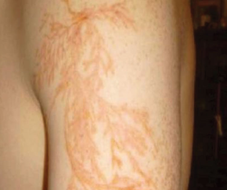
On occasion, persons struck by lightning develop fern-like patterns on their skin [7]. Such patterns do not always form and the mechanisms that govern their formation are not understood. Sometimes the patterns fade away and sometimes they are permanent (Figure 2).
On August 25, 2005, a wildland fire broke out in the Deer Creek area east of Selma in Josephine County, Oregon. Investigation revealed that the fire was caused by a livestock fence energized by an electric fence controller.
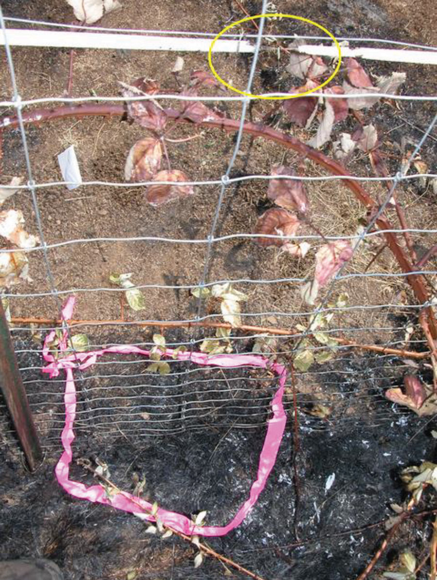
The area of origin was identified by fire investigators Mr. Chuck Miller and Mr. Carl Roberts, and they identified the area of origin as a place where blackberry stalks had not been adequately trimmed to clear the electrically charged fence wires (Figure 3 on page 22). The blackberry and wild mustard plant stalks were collected by the investigators. The immediate significance of Lichtenberg figures observed on the surface of the plant stems was not fully recognized and prompted laboratory inspection. Laboratory testing demonstrated that the application of electrical energy from exemplar fence chargers was able to duplicate these patterns and that temperatures were hot enough to cause ignition of dried vegetation.
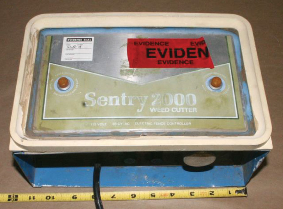
The electric fence controller was a Sentry 2000 Weed Cutter, model number 10-9-110, serial number 44601. Date codes indicated that it was manufactured about September of 1975, and no UL, CSA, or other National Recognized Testing Laboratory (NRTL) marks were found.
The Sentry 2000 fence controller functioned via a step-up transformer that converted the 120-volt 60-Hz line power to approximately 2200 volts AC (Figure 4). A circuit timer caused the output voltage to alternate between approximately 2200 volts AC (approximately 1.36 to 1.52 seconds) and 700 volts AC (approximately 0.72 to 1.04 seconds.). The power output of the Sentry 2000 was measured to be approximately 12 watts with a 100 kilohm load, and the maximum current was 60 milliamperes with a 1 ohm load.
After measuring the output, the incident Sentry fence controller was not used for further testing. A functional exemplar device was located—it was a BullDozer WD-56A, serial number 77678. The unit had the date code “8 87,” indicating it had been manufactured in August 1987, and no UL, CSA, or NRTL marks were found. The electrical output alternated between 1498 volts AC and 900 volts AC with no load (Figure 5).
Livestock touching an energized fence wire receives an electrical shock, which is meant to deter them from breaking through the fence. Vegetation contacting the fence also produces a path to the ground. In late summer, the vegetation dries out and poses a potential fire hazard if ignited.
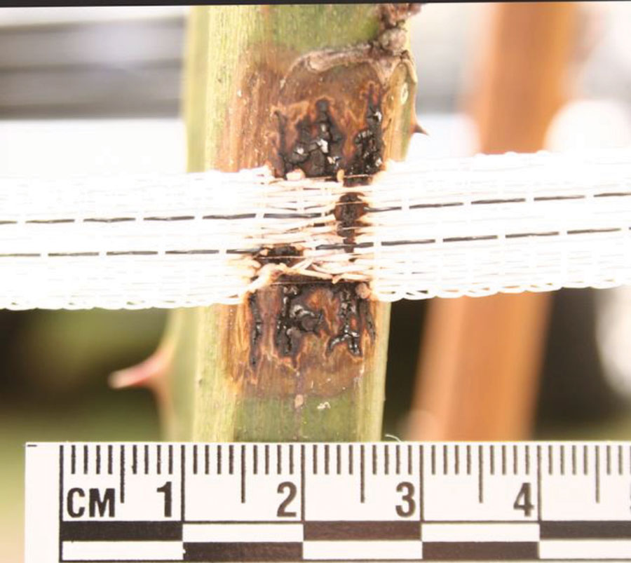
A portion of the fence perimeter used woven plastic with embedded stainless-steel wires (note the melted white plastic of the electrified fence wire circled in Figure 3 and a close-up in Figure 8). Laboratory testing of exemplar plastic fence material indicated that it was high-density polyethylene with a melting temperature of approximately 125 degrees C (257 degrees F). Once ignited, the sample burned readily with self-sustained combustion producing flaming drips.
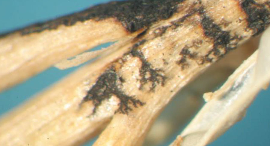
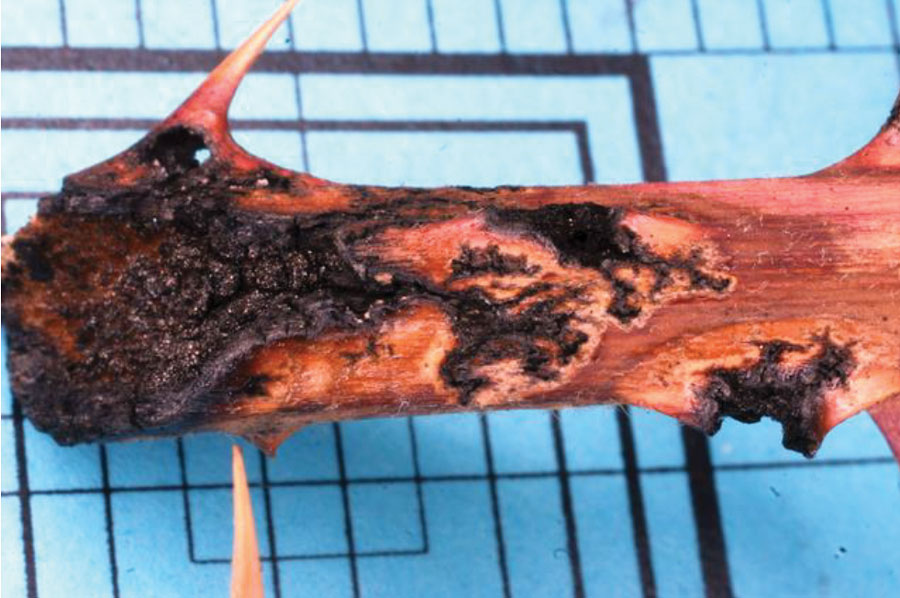
Both the wild mustard stalks (Figure 6), the blackberry stalks (Figure 7), and the test blackberry stalk (Figure 8) showed Lichtenberg figures characteristic of electrical currents flowing through or over the plant.
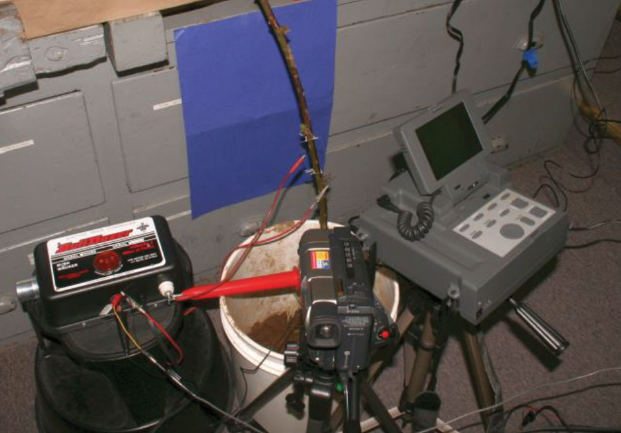
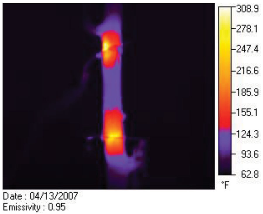
The BullDozer fence controller test setup is shown in Figure 5. The controller was connected to a live potted blackberry stalk by two steel electrodes. The electrodes were spaced approximately 12.7 cm (5 inches) apart. Smoking, scintillation, smoldering, and pyrolysis of the blackberry stalk were observed within 30 seconds of energized output from the fence controller. After about 30 minutes of operation, horizontal bands of deep pyrolysis adjacent to the electrodes, surface discoloration, and fine electrical arc pyrolyzed tracks were observed. These marks matched those found on both the incident blackberry and wild mustard plants. The formation of additional electrical arc tracking and Lichtenberg figures continued to develop for the duration of the test (Figure 9). One thermographic image revealed a spot temperature of approximately 300 °F at the electrode with the controller connected between the electrode and the soil.
Additional testing with the electrodes approximately 12.5 cm apart was conducted and thermographic images showing the temperature profile and spot temperature were recorded (Figure 9). Scintillation, arcing, subsurface heating, and arc track Lichtenberg figures were substantially similar in both electrode tests. Use of the “night shot” mode on the camcorder revealed broader areas of heating below the epidermis of the plant stalk. The spot temperature of the hot electrode was observed to reach over 391 °F. Use of the “night shot” mode on the camcorder revealed broader areas of heating below the surface of the plant stalk.
The visible physical dimensions of the electrical scintillation were below the resolution and sample rate of the thermal camera; however, the color of the incandescent material indicated temperatures of at least 1,000 °F.
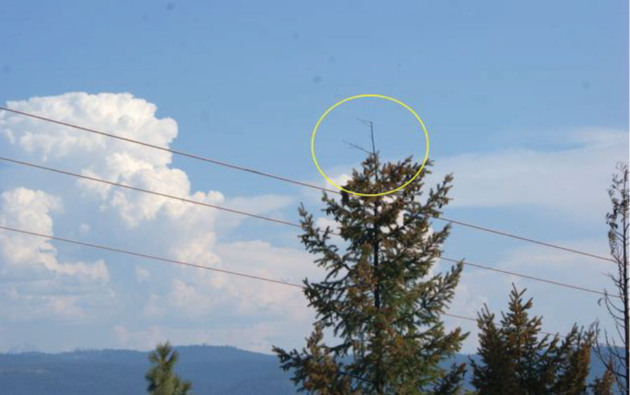
A wildland fire occurred on July 29, 2009 in the Burnt Peak area just north of Lost Creek Lake in Jackson County, Oregon. Fire investigators placed the origin of the fire along the path of a high-voltage power transmission line at the base of an 80-foot-tall Douglas fir tree. A laser-scan survey verified the spacing between the treetop and the transmission line ere close enough to have made contact (Figure 10). The tree had grown tall enough that lateral sway in both the wires and in the tree itself had caused the power transmission lines to intermittently contact the top of the tree. The National Electric Safety Code (NESC), Article 281[8], requires vegetation clearing along the path of power transmission lines to prevent such contact; however, the required lateral clearance as measured on the ground did not take into account seasonal growth in the tree and lateral sway (Figure 11).
The tree was harvested, cut into sections, and stored for later examination. Examination of the most recent three years of growth at the tip of the tree showed alligator burn patterns and, more subtly, Lichtenberg patterns (Figure 12). The cause of the fire was confirmed to be due to smoldering brands falling from the tree where it had come into contact with the transmission line.
On August 20, 2004, a wildland fire occurred in the vicinity of Bland Mountain in Douglas County, Oregon. Fire investigators placed the origin of the fire adjacent to a fence electrically energized by a Dyna-Charge Model 900 electric fence charger. The fire started on an open west-facing slope at approximately 4:50 pm. The Dyna-Charge fence controller was listed as being in compliance with UL 69.
The conditions at the Bland Mountain lookout were 79 °F and 45% RH (relative humidity) with a 1–3 mile per hour (0.45–1.30 m/s) southeasterly breeze.
The key feature offered by this kind of fence charger is the notion that the short duration of the pulses makes ignition unlikely. Nature, however, proved to be more variable and presented conditions that eventually did lead to ignition.
The Dyna-Charge fence controller was UL listed as being in compliance with UL 69. In conversation with a UL representative, I was reminded that testing to a standard does not confer any assurance that the test conditions replicate real-world conditions.
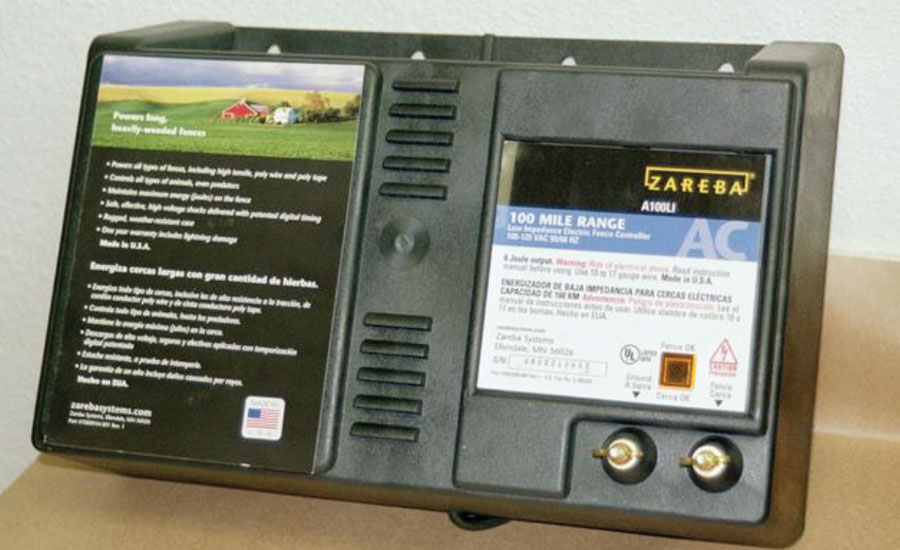
An exemplar for the Dyna-Charge 900 was identified as a Zareba A100 LI fence controller. Zareba appears to have acquired the Dyna-Charge design (Figure 13). The incident unit was energized to confirm proper operation, and further testing was performed using the exemplar Zareba unit. Initial testing was in accordance with UL 69. The purpose of the tests was to determine whether the Zareba could ignite dried vegetation under laboratory conditions. The Zareba was rated to provide six (6) joule pulses suitable for energizing 100 miles of fencing. The unipolar pulses were approximately 13 kV in amplitude and approximately 120 µs in duration. Current pulses under some loads reached approximately 23 amperes.
While UL 69, Standard for Electric Fence Controllers, governs the testing and compliance certification of electric fence chargers, such testing standards cannot anticipate all possible field conditions that might cause ignition. The standard provides for testing the propensity for discharge-caused ignition; however, it primarily deals with the electrical safety and fire hazard posed by the equipment itself, and not as might be caused by the discharges along the fence line.
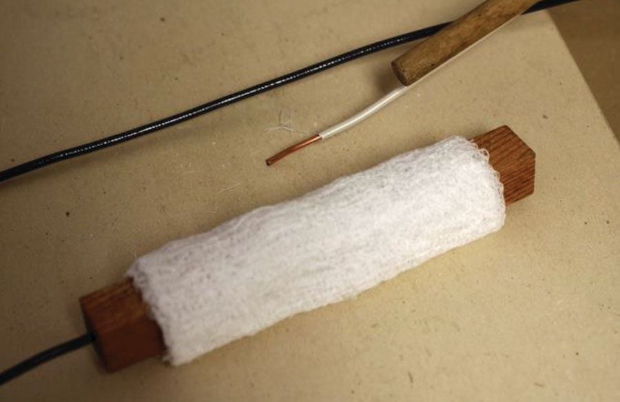
The basic procedure is to prepare a block (or dowel) of wood by first desiccating and then soaking it in a saline solution of prescribed concentration (Figure 14).
The block is again dried and wrapped in cheesecloth. One of the electrode wires is inserted into a hole drilled in the block, while the other wire rests on the outside of the cheesecloth. Testing continues for 15 minutes; if no ignition or charring of the cheesecloth occurs, then the device passes the test.
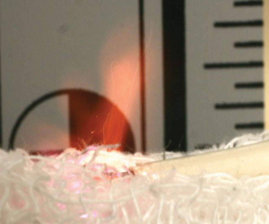
The Zareba A100 LI easily passed the requirements of UL 69 sections 22 and 32. However, when the bench test was extended in duration, the pulse discharges eventually penetrated the wooden block. Each subsequent pulse ejected an incandescent plume with microscopic brands (incandescent embers (Figure 15). Given a suitable first fuel, such as cottonwood fluff, or the fortuitous delivery of a brand into a clump of dry grass, this could result in ignition.
The UL 69 standard does not guarantee that the device cannot, or will not, cause fire under all field conditions. A pulse every 1.25 seconds, day in and day out, will amount to over a million pulses in 14 days. Each six-joule pulse poses an opportunity for the pulse to ignite an errant piece of vegetation or cottonwood seed fluff.
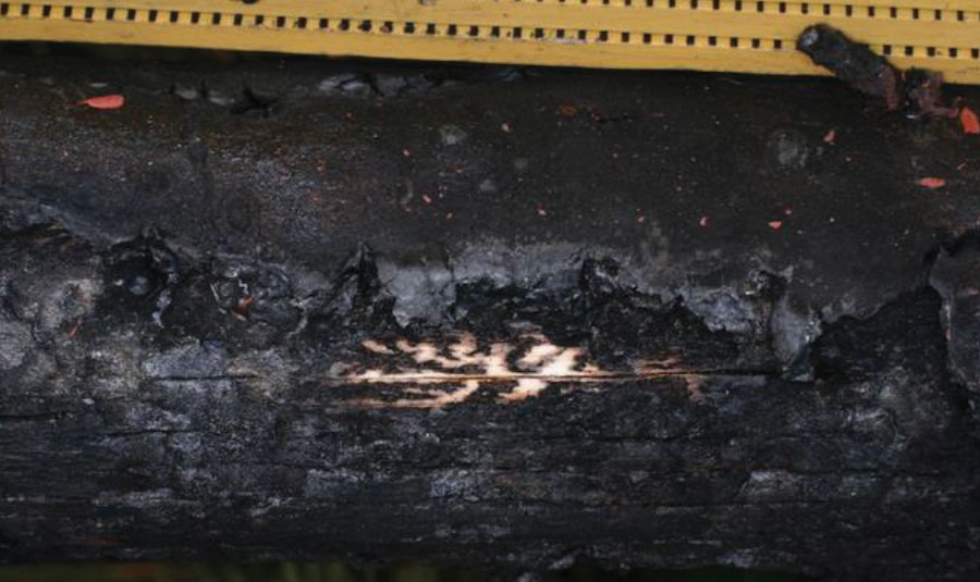
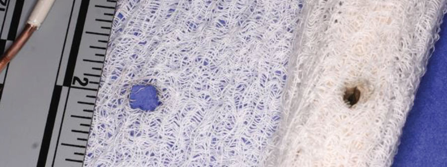
The testing was allowed to continue, and after about 15 minutes, the charger pulses burned a hole in the side of the wooden test block (Figure 16). Incandescent ejecta was observed. Even though the ejecta charred the cheesecloth test material, they did not cause ignition under laboratory conditions.
It would be too easy if all electrical currents through live vegetation formed Lichtenberg figures. The AC power from the transmission lines and the neon-sign high-voltage fence controllers can form Lichtenberg figures but do not always do so. The 13 kV pulses from the Zareba controller did not produce Lichtenberg figures but instead produced potentially incendive plumes that erode plant material without leaving Lichtenberg figures.
While researching the early stages of ignition associated with electric arcs, Dr. Thomas Pratt mentions in his book, Electrostatic Ignition, that arc has multiple factors to be considered, including inductance. In conversation with engineers at Zareba (2007), inductance was not part of their fence model, nor was it part of the UL 69 standard. The series inductance of the fence wire for the Bland Mountain fire was measured to be 1 mHenry.
Also, while researching how brands, embers, or smoldering ignition (initiated by electrical current) could transition to open flame, clues were found in two sources: Jack Sanderson’s Fire Findings [9] and Dr. Babrauskas’ Ignition Handbook [10]. Sanderson reported trying to replicate the conditions for smoldering ignition of denim on a chair cushion, and, out of 500 trials, none of them transitioned to open flame. He reported that with the addition of a ceiling fan producing a nominal 2.1 mile per hour (approximately 0.94 m/s) breeze, ignition occurred “fairly dependably.” Dr. Babrauskas mentions that transition from smoldering to open flame happened most frequently with a 2 to 3 mile per hour breeze in wildland fires. And, as mentioned earlier, brands are incandescent embers that can be lofted by a breeze or can fall to the ground and act as an ignition source. They are particularly incendive.
The Deer Creek fire was on a south-facing grassy slope in late summer, and the Burnt Peak fire also occurred on a slope. It is likely that an up-slope breeze helped these fires transition from smoldering to open flame.
In wildland fires, seasonal vegetation (such as cottonwood fluff), ambient humidity, and vegetation moisture content are significant variables. A means to directly assess moisture content should be employed—that is, the vegetation samples can be weighed on-site before being bagged, and similarly, exemplar vegetation of comparable dimension and quantity could also be weighed before being bagged.
Electrical currents form Lichtenberg figures visible in the epidermis of several very structurally different plants, including trees (Douglas Fir), Himalayan Blackberry, and wild mustard.
Lichtenberg figures form in plants by resistance heating due to the flow of electrical current. Pyrolytically formed Lichtenberg figures can be, and normally are, obliterated by subsequent combustion of the base material.
Patterns of initial similar appearance may form due to botanical diseases; however, electrically formed patterns show material loss. Identification may require microscopic examination.
Temperatures created by the flow of current from the tested electric fence controllers were sufficient to cause ignition. While the probability of ignition may be low under some conditions, the continuous long-term persistence of an ignition source plus the continuous variation in the environmental conditions provided multiple repeated opportunities for ignition.
An investigator should anticipate collection of incident equipment, vegetation, wiring, and exemplar equipment and should also take weather measurements and moisture content of potential first ignited fuels.
Laboratory tests showed that even the UL 69 test caused the ejection of incandescent embers during discharges from some fence charger models (like the Zareba).
Pulsed fence chargers caused discoloration of the blackberry stalks but did not create Lichtenberg figures.
Manufacturers may need to test their products beyond the letter of the UL standards to accurately determine product safety, as UL test standards are minimum requirement standards.
When testing the mutual competency of an ignition source and potential first-fuels-ignited, ambient humidity and the test fuel moisture content must be adequately understood and controlled.
A gracious thank you to Chuck Miller and Carl Roberts for their excellent fieldwork and their coaching in wildland fire investigation. Thanks also go to Jeff Bonebrake of the Oregon Department of Forestry for permission to use photographs and test results from the related investigations. Not least, thank you to the administrative and engineering staff of Engineering Systems Inc. for their scrupulous review of this paper.
- “De Nova Methodo Naturam Ac Motum Fluidi Electrici Investigandi,” Göttinger Novi Commentarii, Göttingen, 1777. The English translation from the Latin title is “Concerning the New Method of Investigating the Nature and Movement of Electric Fluid.”
- Electrolytic Electromigration of Metallic Material and Silver Filled Epoxy, Design for Reliability Software Company, https://www.dfrsoft.com/DfRSoft_Ag-Migration.pdf, accessed 2/29/20.
- Joseph, Michael L., “A Geochemical Analysis of Fulgurites: from the inner glass to the outer crust,” January 2012, http://scholarcommons.usf.edu.
- Blodgett, R. B. , “Ethylene Propylene Rubber and Crosslinked Polyethylene as Insulations for 90°C Rated Medium Voltage Cables,” Rubber Chemistry and Technology, May 1979, Vol. 52, No. 2, pp. 410-424.
- Niemeyer, L., Pietronero, L., Wiesmann, H. J. “Fractal Dimension of Dielectric Breakdown,” Physical Review Letters, American Physical Society (APS), March 19, 1984, Vol. 52, Issue 12, pp. 1033–1036.
- NFPA 921, Guideline for Investigation of Fires and Explosions, 2017 ed., National Fire Protection Association, Chapter 3 Definitions, p. 16.
- Cherington, Michael, Olson, Sheryl, and Yarnell, Philip R., “Lightning and Lichtenberg Figures,” Injury: International Journal of the Care of the Injured, Vol. 34, Issue 5, May 2003, pp. 367-371
- National Electric Safety Code (NESC), 2019 ed., IEEE Press, doi:10.1201/9781420052015-17.
- Fire Findings, Vol 15, No. 3, Summer 2007.
- Babrauskas, V., Ignition Handbook, First Edition, July 2003, Fire Science Publishers, Issaquah, WA, USA, ISBN: 978-0-9728111-3-2.

