he selection of component values for common mode filters need not be a difficult and confusing process. The use of standard filter alignments can be utilized to achieve a relatively simple and straightforward design process, though such alignments may readily be modified to utilize pre-defined component values.
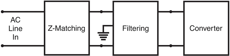
Line filters prevent excessive noise from being conducted between electronic equipment and the AC line. Generally, the emphasis is on protecting the AC line. Figure 1 shows the use of a common mode filter between the AC line (via impedance matching circuitry) and a (noisy) power converter. The direction of common mode noise (noise on both lines occurring simultaneously referred to as earth ground) is from the load and into the filter, where the noise common to both lines becomes sufficiently attenuated. The resulting common mode output of the filter onto the AC line (via impedance matching circuitry) is then negligible.
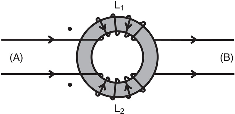
The design of a common mode filter is essentially the design of two identical differential filters, one for each of the two polarity lines with the inductors of each side coupled by a single core (see Figure 2).
For a differential input current ((A) to (B) through L1 and to (A) through L2), the net magnetic flux which is coupled between the two inductors is zero.
Any inductance encountered by the differential signal is then the result of imperfect coupling of the two chokes. They perform as independent components with their leakage inductances responding to the differential signal, and the leakage inductances attenuate the differential signal.
When inductors L1 and L2 encounter an identical signal of the same polarity referred to ground (common mode signal), they each contribute a net, non-zero flux in the shared core. The inductors thus perform as independent components with their mutual inductance responding to the common signal: the mutual inductance then attenuates this common signal.
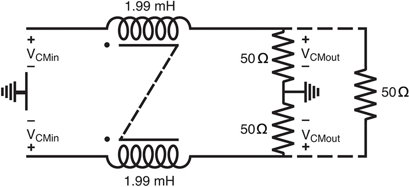
The value of inductance required of the choke is simply the load in Ohms divided by the radian frequency at and above which the signal is to be attenuated.
For example, attenuation at and above 4000 Hz into a 50Ω load would require a 1.99 mH (50/(2π x 4000)) inductor. The resulting common mode filter configuration is shown in Figure 3.
The attenuation at 4000 Hz would be 3 dB, increasing at 6 dB per octave. Because of the predominant inductor dependence of a first order filter, the variations of actual choke inductance must be considered. For example, a ± 20% variation of rated inductance means that the nominal 3 dB frequency of 4000 Hz could be anywhere from 3332 Hz to 4999 Hz.
It is typical for the inductance value of a common mode choke to be specified as a minimum requirement, thus ensuring that the crossover frequency not be shifted too high. However, some care should be observed in choosing a choke for a first order low pass filter because an inductance with a much higher than typical or minimum value may limit the choke’s useful band of attenuation.
The design of a second order filter requires more care and analysis than a first order filter to obtain a suitable response near the cutoff point, but there is less concern needed at higher frequencies, as previously mentioned.
One of the critical factors involved in the operation of higher order filters is the attenuating character at the corner frequency. Assuming tight coupling of the filter components and reasonable coupling of the choke itself (conditions we would expect to achieve), the gain near the cutoff point may be very large (several dB). Moreover, the time response would be slow and oscillatory. On the other hand, the gain at the crossover point may also be less than the presumed -3 dB (3 dB attenuation), providing a good transient response, but frequency response near and below the corner frequency could be less than optimally flat.
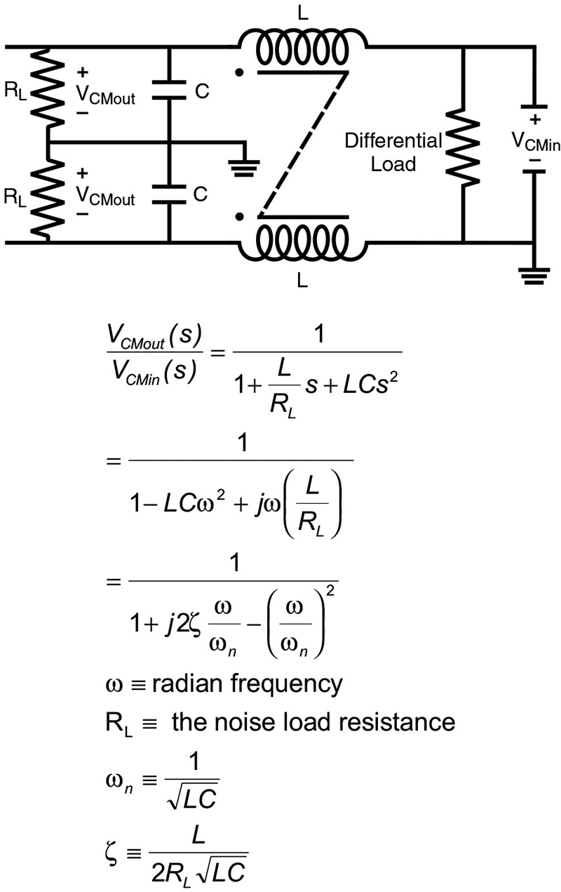
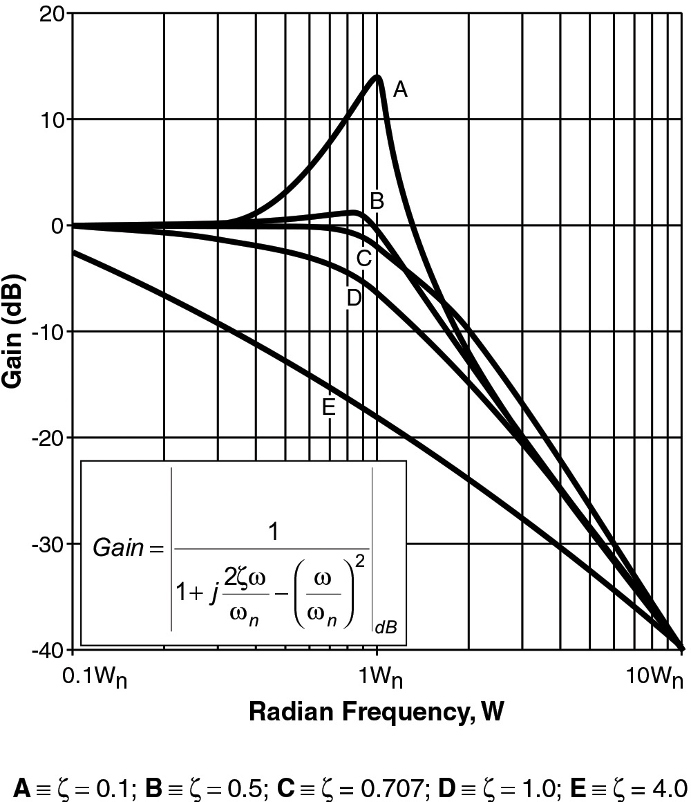
In the design of a second order filter, the damping factor (usually signified by the Greek letter zeta (ζ)) describes both the gain at the corner frequency and the time response of the filter. Figure 5 shows normalized plots of the gain versus frequency for various values of zeta.
As the damping factor becomes smaller, the gain at the corner frequency becomes larger, and the ideal limit for zero damping would be infinite gain. The inherent parasitics of real components reduce the gain expected from ideal components but tailoring the frequency response within the few octaves of critical cutoff point is still effectively a function of ideal filter parameters (i.e., frequency, capacitance, inductance, resistance).
For some types of filters, the design and damping characteristics may need to be maintained to meet specific performance requirements. However, for many actual line filters, a damping factor of approximately 1 or greater and a cutoff frequency within about an octave of the calculated ideal should provide suitable filtering.
The following is an example of a second order low pass filter design:
- Identify the required cutoff frequency—For this example, suppose we have a switching power supply (for use in equipment covered by UL 478) that is 24 dB noisier at 60 kHz than permissible for the intended application. For a second order filter (12 dB/octave roll-off), the desired corner frequency would be 15 kHz.
- Identify the load resistance at the cutoff frequency—Assume RL = 50 Ω
- Choose the desired damping factor—Choose a minimum of 0.707, which will provide 3 dB attenuation at the corner frequency while providing favorable control over filter ringing.
- Calculate required component values using the following equations:
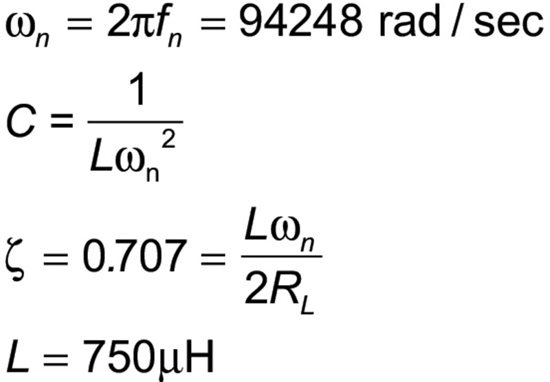
- Choose available components as follows:
C = 0.05 µF (Largest standard capacitor value that will meet leakage current requirements for UL 478/ CSA C22.2 No. 1: a 300% decrease from design)
L = 2.1 mH (Approximately 300% larger than design to compensate for reduction or capacitance) - Calculate actual frequency, damping factor, and attenuation for components chosen using the following equations:
- ζ = 2.05 (a damping factor of about 1 or more is acceptable
Attenuation = (12 dB/octave) x 2 octaves = 24 dB - The resulting filter is that of Figure 4 with:
L = 2.1 mH; C = 0.05 µF; RL = 50 Ω
Note: Damping factors much greater than 1 may cause unacceptably high attenuation of lower frequencies, whereas a damping factor much less than 0.707 may cause undesired ringing and the filter may itself produce noise.
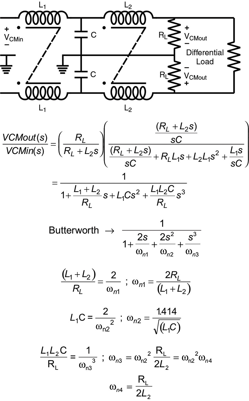
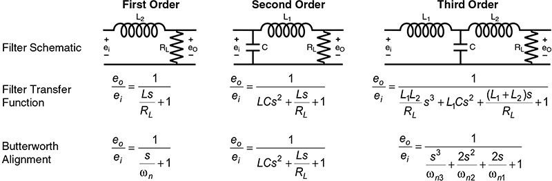
The design of a generic filter is readily accomplished by using standard alignments such as a maximally flat alignment (also known as a Butterworth alignment). Figure 6 shows the general analysis and component relationships to the Butterworth alignments for a third order low pass filter. Butterworth alignments provide an inherent z of 0.707 and a -3 dB point at the crossover frequency. The Butterworth alignments for the first three orders of low pass filters are shown in Figure 7.
- First design a second order low pass with ζ ≥ 0.5;
- Add a third pole (which has the desired corner frequency) by cascading a second inductor between the second order filter and the noise load so that:
L = R/ (2 π fc)
Where fc is the desired corner frequency.
- List the desired crossover frequency, load resistance:
Choose fc = 15000 Hz
Choose RL = 50 Ω - Design a second order filter with ζ = 0.5 (see second order example above)
- Design the third pole:
RL/(2πfc) = L2
50/(2π15000) = 0.531 mH - Choose available components and check the resulting cutoff frequency and attenuation:
L2 = 0.508 mH
fn = R/(2πL1 ) = 15665 Hz
Attenuation at 60 kHz: 24 dB (second order filter) + 2.9 octave × 6 = 41.4 dB - The resulting filter configuration is that of Figure 6 with:
L1 = 2.1 mH
L2 = 0.508 mH
RL = 50 Ω
A step-by-step design procedure may utilize standard filter alignments, eliminating the need to calculate the damping factor directly for critical filtering. Line filters, with their unique requirements, yet non-critical characteristics, are easily designed using a minimum allowable damping factor.
Standard filter alignments assume ideal filter components, but this does not necessarily hold true, especially at higher frequencies.