The Untold Electromagnetic Backstory

n February 1, 2003, NASA’s Space Shuttle Orbiter Columbia broke apart upon re-entry into the earth’s atmosphere, tragically ending the lives of seven highly-trained and experienced astronauts. This accident not only personally affected the extended families of the astronauts, it permanently changed the trajectory of the U.S. manned space program. After a lengthy accident investigation and root cause analysis, the Shuttle successfully flew again on July 26, 2005. The Shuttle’s subsequent 22 missions made possible the completion of the assembly of the International Space Station (ISS) and provided a final service call for the Hubble Space Telescope, before the Shuttle fleet was retired in 2011.
While much has been written about the Shuttle program, this specific article will focus on a very little-known element of the Shuttle’s return-to-flight (RTF) story. Beginning with the Columbia investigation and ending with the creation and deployment of the NASA Ascent Debris Radar (NDR) System, this article will cover the “Electromagnetics (EM) Backstory” that was instrumental in allowing the Shuttle to safely fly again.
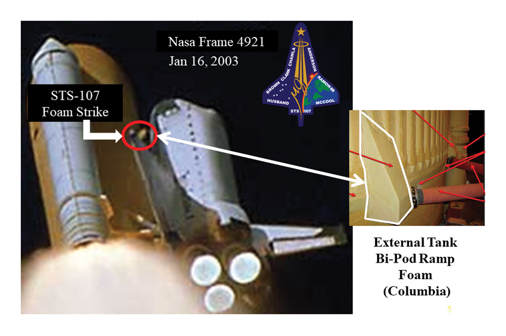
Summarizing the CAIB’s final [1] report, we quickly home in on the root cause sequence. During Columbia’s ascent on January 16, 2003, the left main tank bi-pod ramp insulation foam broke off the external tank about 81.9 seconds into the flight and struck Columbia’s left wing (an image from a NASA launch camera is shown in Figure 1). Unbeknownst to NASA Mission Control or the astronauts on board, the strike damaged and left a hole in the reinforced carbon-carbon (RCC) leading edge around panel 8 of the left wing. The RCC is considered “hot structure” and the RCC protects the interior aluminum wing structure from the frictional heat of re-entry.
Note that Figure 1 is a highly enhanced image produced after the accident, and was not available during the actual mission. In addition, due to the positions of ground cameras and those available on orbit, there was not a clear line of sight to the damaged wing area. NASA material engineers estimating the physics of the kinetic impact suggested a possibility of RCC edge damage. Sadly, there was a lack of program-wide consensus that the wing RCC edge was compromised until the fatal re-entry day.
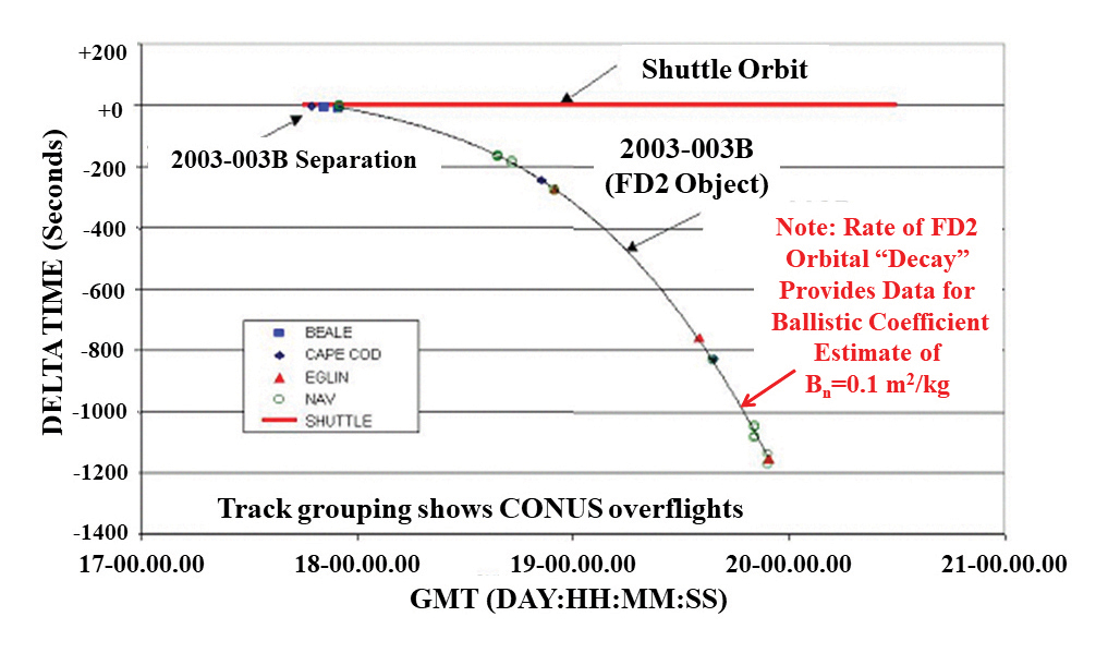
The third and most circuitous path was the EM investigation into the mysterious so-called “flight day two” (FD2) object. During its second day in orbit, when the Columbia was flying in an upside down and backward direction relative to its orbital velocity vector, Columbia performed a slight yaw maneuver to calibrate an on-board navigation sensor, then re-maneuvered to return to its base orbit. Right after this maneuver, low frequency USAF space monitoring radars automatically detected the departure of a small debris piece from Columbia, as shown in the tracking radar data in Figure 2.
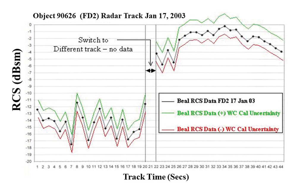
As a radar signature expert, I must explain that every radar target has a property called “radar cross section” (RCS) that is a measure of how an object scatters radar energy in all directions. Generally RCS is denoted by the symbol Ó, with SI units of m2 or dBsm. RCS generally varies with the frequency of the radar and 32the orientation of the target with respect to the radar. Since the FD2 object tumbled in space, ground radar sensors saw a varying RCS versus time.
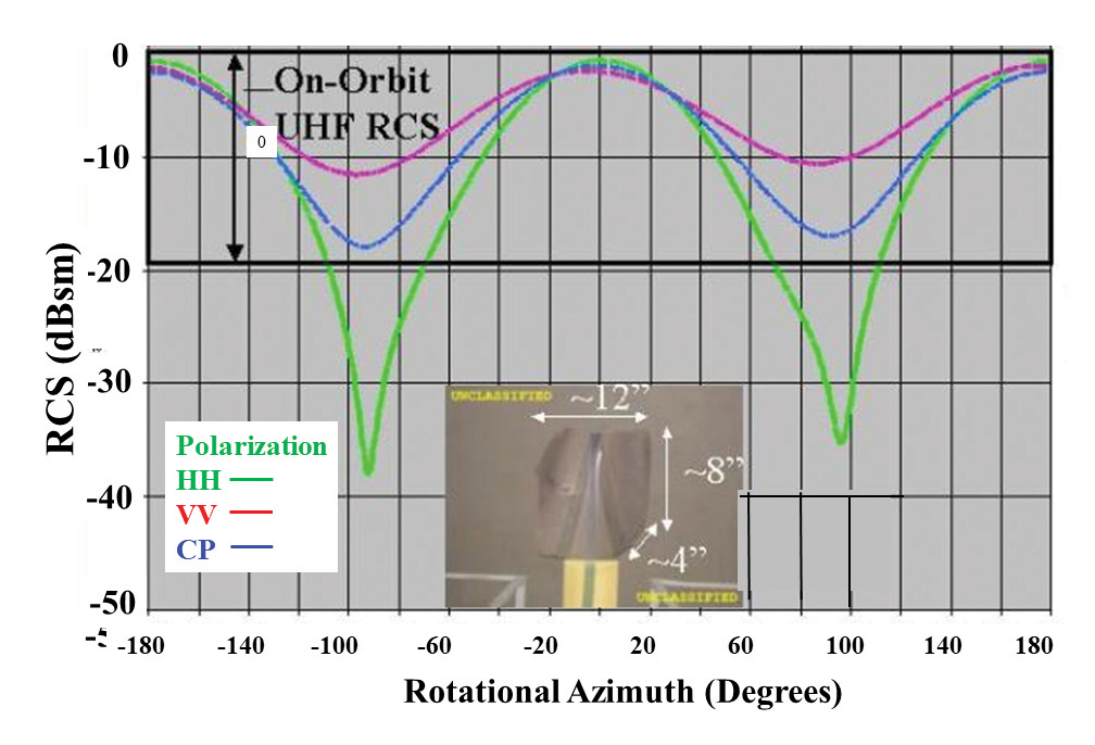
After the CAIB investigation began, U.S. Air Force Space Command (AFSPC) analysts determined the aeronautical ballistic coefficient (Bn) from the shape of the ballistic re-entry profile in Figure 2. This meant NASA now had two pieces of technical information about the FD2 object: 1) the RCS at 433 MHz of the object varied between -1 and -20 dBsm +/- 1.33 dB; and 2) its average ballistic coefficient, Bn = 0.1 m2/kilogram +/- 15%. What we didn’t know was FD2’s absolute size as we did not have access to the actual FD2 object itself.
Nonetheless, Air Force Research Laboratory (AFRL) was contacted and I was assigned to investigate whether it was possible to narrow down the potential material candidate of the FD2 object to determine if the FD2 object was relevant to the CAIB investigation.
By February 12th, 2003, I was paired up with Steve Rickman of NASA-JSC, then Chief of the Thermal Design Branch. Rickman’s organization was home to subject matter expertise and had responsibility for the Space Shuttle Orbiter Thermal Protection Subsystem (TPS), and the RCC Leading Edge Structural Subsystem (LESS). His team also was familiar with the Thermal Control System (TCS) materials present on the inside of the payload bay.
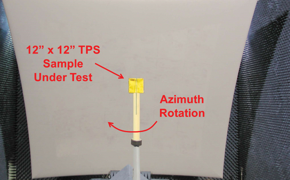
Rickman’s team worked with our AFRL team to analyze 24 different potential Shuttle material candidates and provided AFRL with representative samples of all 24 materials. AFRL conducted subsequent RCS measurements in a laboratory called the Advanced Compact Range (ACR) which precisely measured the RCS of these material targets at 433 MHz (see Figure 4). The AFRL team quickly built up a database of possible material RCS characteristics, while NASA independently calculated the area to mass or Bn ratio values for these same materials. Our hope was to reduce the possible number of potential Shuttle material candidates.
During this on-going FD2 RCS analysis, NASA mission specialists mentioned that, in previous Shuttle flights, maintenance tools inadvertently left in the payload bay had floated away. To include the possibility that a lost maintenance tool could have floated out of the payload bay, the CAIB audited the tool record logs for Columbia’s three previous pre-flight maintenance cycles. The CAIB found that only three tools (a screwdriver, a snap crimping tool, and a specialized fastener tool) were unaccounted for. This didn’t mean the tools were necessarily on-board Columbia, but only that they were not accounted for in the ground maintenance logs. Nevertheless, AFRL obtained copies of these three tools, and performed RCS tests that definitively eliminated these tools from consideration as the FD2 object.
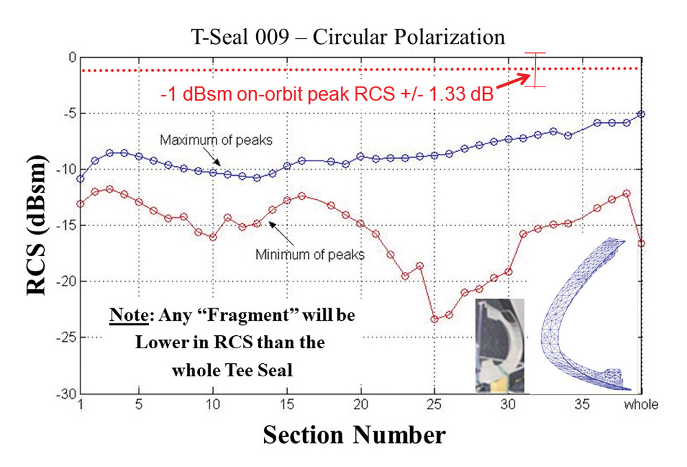
After compiling our test results, the AFRL-NASA FD2 team briefed the CAIB in private testimony on April 13, 2003, then publicly on May 6, 2003. This was weeks before the definitive July 7, 2003 Southwest Research Air Cannon test. [3] The remaining three material candidates included: 1) a fractured “acreage” piece (Figure 5) of the RCC edge segment of at least 90-140 in2 originating from RCC panels 8, 9, or 10, panels which are thicker than the other 19 RCC edge sections and whose acreage pieces would be too light to meet the Bn test criteria; 2) an “RCC “tee seal” that fills the joints between wing edge segments had some initial test ambiguities and wasn’t immediately eliminated; and 3) a large piece of Incoflex “ear muff” spanner beam insulator composed of a cerachrome alloy that was present between the RCC edge and the aluminum spar of the leading edge.
Muratore had three areas of emphasis; 1) study all previous historical Shuttle launches prior to Columbia to assess any and all previous debris releases and their potential sources, 2) re-examine the Shuttle stack design elements (Orbiter plus 2 booster rockets plus the entire external tank) from first principles with an emphasis to change designs that reduced debris events; and 3) put together a safety net of optical and radar sensors that closely monitored the Shuttle during the launch and ascent phases to definitively detect/capture debris releases. This information would promptly be provided to the Mission Control flight director on any perceived safety hazards due to liberated debris striking the Shuttle stack.
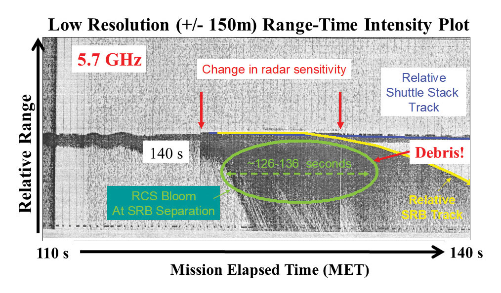
I assisted with the historical study of radar debris tracks and also provided technical assistance on the new debris radar sensors. By September of 2003, Griffith and I recruited a diverse team of EMI/EMC, radar and weather experts from NASA-JSC, the U.S. Navy (USN), MIT Lincoln Laboratory, Mission Research Corporation, and the Air Force. The radar team had two primary duties. We first worked to support Muratore’s thrust of pouring over archived tracking radar from previous Shuttle flights prior to Columbia. In the process, we discovered both optical and radar records of debris separation events especially near, during, or shortly after solid rocket booster separation. Figure 7 shows legacy radar debris data from a low-resolution tracking radar at NASA-KSC. Since the radar resolution was ~+/-150 meters, this tracking radar didn’t give insight into the debris environment, especially debris considered “normal.”
Any potential NASA debris radar (NDR) sensor had to be sited to get a lateral side view of the ascending Shuttle, which ultimately eliminated all possible radar sites southwest of the Shuttle launch pads 39A and 39B, where all current USAF tracking radars were located. The NDR team needed a site to the northwest of the cape, potentially on the grounds of a U.S. Park Service National Wildlife Refuge. How was that going to happen?
The technology recommended by the radar team was already deployed on USN ship platforms for monitoring western pacific test launches of mobile ICBMs. Furthermore, the USN had recently decided to relocate a $50 million C-band radar from Puerto Rico and were looking for a replacement site in Bermuda or Florida. The USN also supplied technical contacts in Denmark for a Weibel high resolution Doppler radar that worked in the velocity range needed during Shuttle ascent.
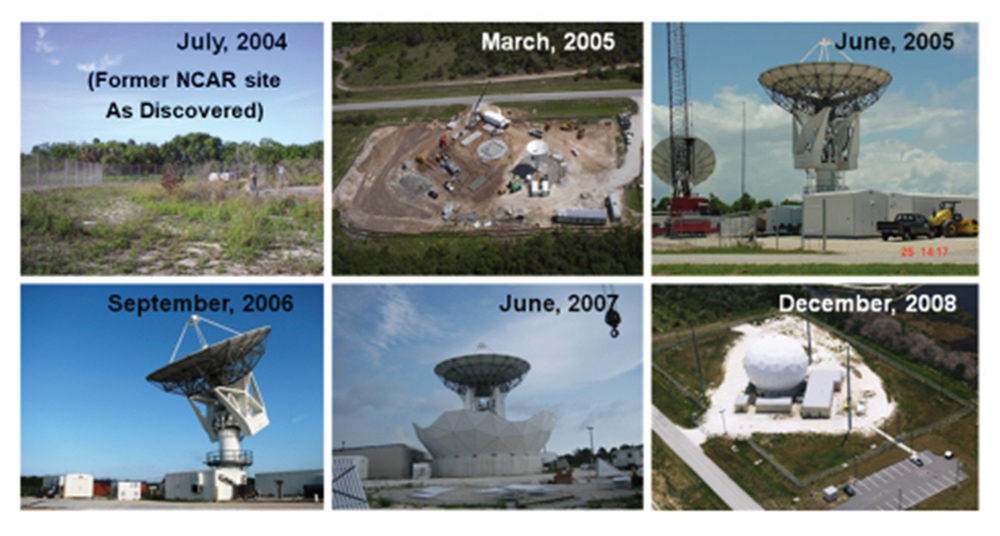
The USN’s Charlie McSorley, Mike Hardman, and Marty Stuble jointly spearheaded efforts between the Navy and NASA to get the C-band radar moved. Ultimately, NASA executed a joint agreement with the USN to relocate the C-band radar near Kennedy Space Center. Recall that our plume RCS results required us to site the USN C-band radar for a lateral launch view. Since all big projects need at least some luck, the NDR team finally got a break. We found a small fenced-off 0.5-acre plot on Merritt Island sited to the NNW of Pad 39A. This plot formerly sited a thunderstorm research radar for the National Center for Atmospheric Research (NCAR). The NCAR radar was long gone, but the perimeter fenced land still belonged to NCAR even though it was now on a National Wildlife Reserve. NASA and NCAR quietly and efficiently transferred the property to NASA on permanent loan, and NDR had its radar site!
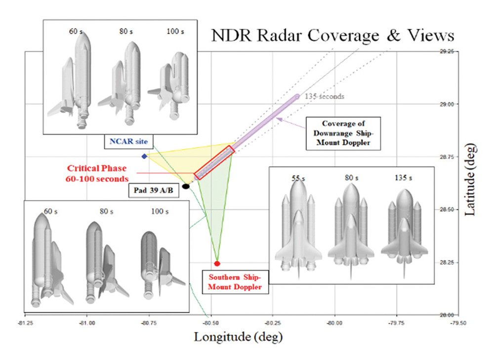
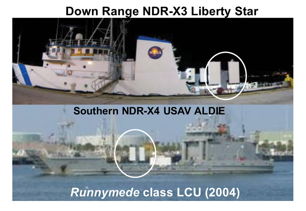
The photo sequence in Figure 11 shows the original 2004 NCAR site and its transformation to its present form. Figure 12 shows the combined “field of view” of the ascending Shuttle as seen from the fixed C-band NCAR site plus the two, ship-deployed X-band Doppler radar sites. Figure 13 shows the two Dutch-made Weibel Doppler radars deployed downrange on the NASA SRB recovery vessel Liberty Star and on a U.S. Marine Runnymede class LCU.
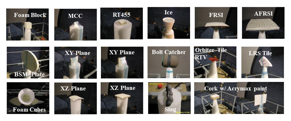
Meanwhile, NASA-JSC created a database of matching ballistic coefficient, Bn, for each candidate. This involved hundreds of RCS measurements of everything from various pieces of tank foam, cork insulation, space-qualified RTV sealant and so forth. Each sample was measured from 2-18 GHz, 360° in azimuth, and for three X-Y-Z orientations. The observable signatures were medianized over observable tumbling angles (like liberated debris in free stream air) and their corresponding Bn numbers included. Figure 14 shows a small sample of materials whose RCS was characterized in the ACR.
At the conclusion of these RCS tests, we had a very good feel for the combined RCS and Bn for nearly every Shuttle material. What we didn’t know was whether the NDR system radars, which operated at fairly high powers, would interfere with the operational Shuttle systems during launch and ascent. It was a safety concern that NASA demanded be addressed before return to flight.
After the acquisition of the NDR system was approved, Shuttle EMI engineers realized these three new monitoring radars would emit frequencies to which the Shuttle had not been exposed during previous launch and ascent operations. The new “debris” radars were to operate in two specific frequency bands, with the C-band radar emitting an FM sweep continuously from 5.45 GHz to 5.95 GHz, and the new X-band “Weibel” Doppler radars tunable to any fixed frequency between 10.0 GHz to 10.55 GHz. Clearly, it became imperative to verify that the new C-band and X-band debris radars would not interfere with any existing Shuttle system during the ascent phase. Since the aft bay of the Shuttle houses the critical Space Shuttle Main Engine (SSME) controllers, NASA was particularly concerned about RF exposure of sensitive equipment inside the aft bay to exterior radar RF levels from outside the aft bay. Fundamental knowledge of the RF shielding characteristics was required before Discovery could be certified for safe flight.
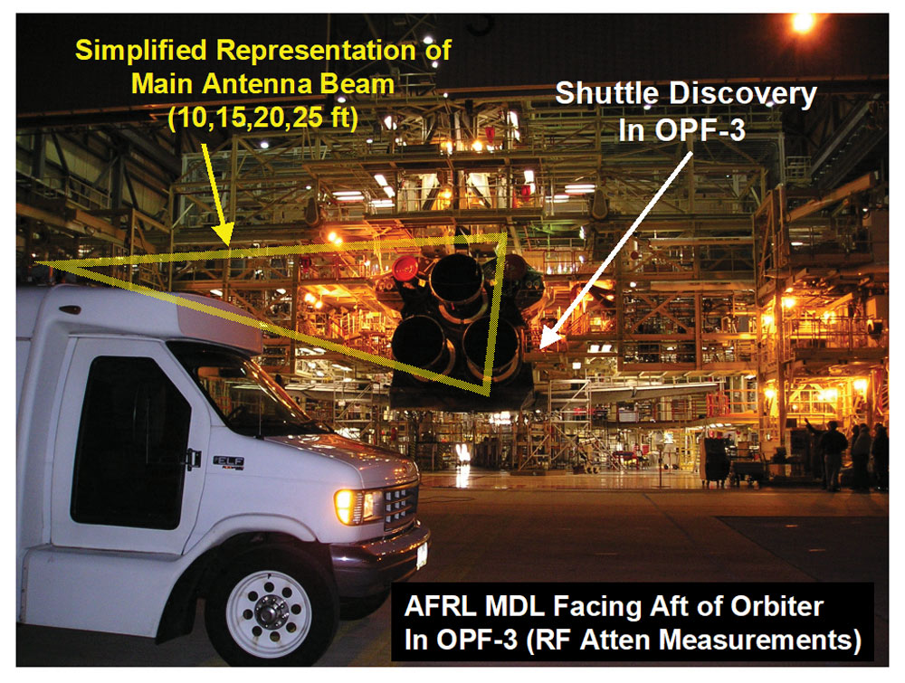
The purpose of the EMI test was to provide NASA an accurate estimate of the RF attenuation at specific radar frequencies of the Orbiter Aft engine bay, including an estimate of measurement uncertainty. The measurements had to be performed while the Shuttle was contained in a hangar-like facility called the orbiter processing facility (OPF). The relative geometry of the Shuttle and the OPF high-bay (HB) 3-door area along with the test receiver is shown in Figure 16. (Note the Shuttle Discovery was located inside OPF 3, and the hanger doors were opened so that the RF attenuation measurements could be made outside.)
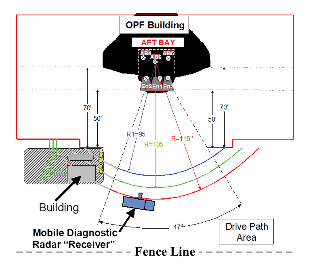
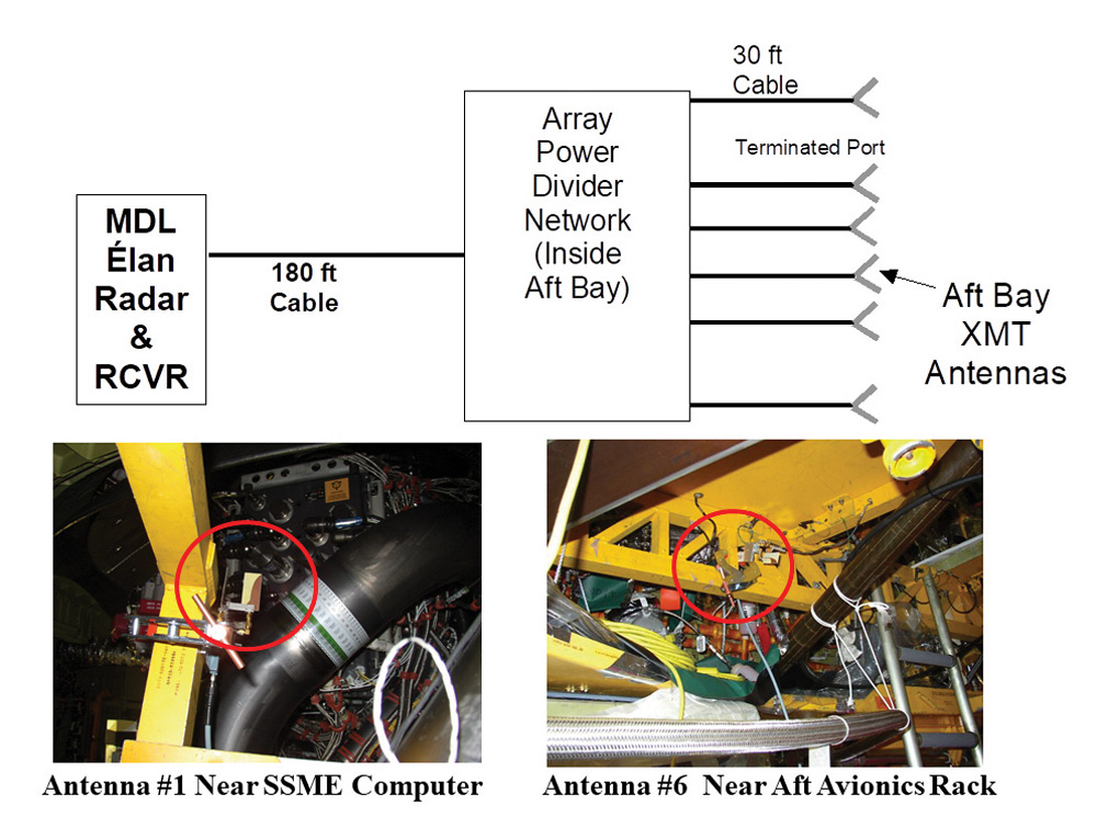
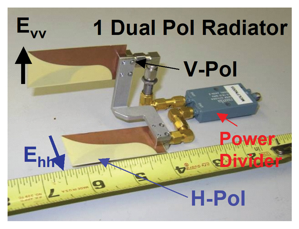
The orbiter Discovery was in preparation to launch around mid-July 2005. To assure this RF attenuation measurement data was flight representative, AFRL needed the Orbiter in the closest possible state to flight. It was essential that the AFRL MDL EMI/EMC test did not impact Discovery’s flight schedule. For this reason, we came up with a reasonable test configuration that minimally impacted the Orbiter schedule. Since EM reciprocity allows one to interchange source and receive antennas in a one-way RF measurement, we decided to place the RF radiators inside the Aft engine bay, then measure the RF leakage with a passive receiver positioned outside the vehicle. Since the aft engine bay is physically large, the test team decided to place six, dual-polarized radiating antenna elements inside the aft bay, all connected together with a commercial off-the-shelf (COTS) RF feed network.
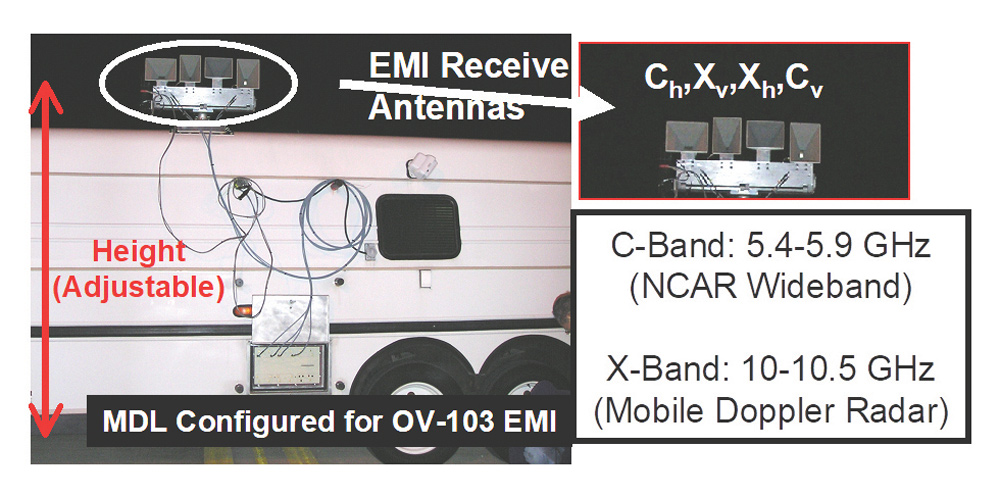
To receive the energy, AFRL positioned their mobile diagnostic laboratory (MDL) [7,8] in a receive-only mode as indicated earlier. To help reduce unintentional local electromagnetic interference (EMI) during the RF attenuation measurements, we used the existing MDL radar as the exciter, running a long, fixed cable between the transmitter and the aft bay emitters. During a typical RF attenuation measurement, the MDL was driven along a fixed radius circle relative to a point in the center of the aft bay. The receiver was triggered at regular intervals along the radius, and measurements were performed for all radar bands and polarizations, three ranges and four antenna heights. C-band data was acquired from 5.45-5.95 GHz, while X-band Data was acquired from 10.0-10.5 GHz. Figure 17 shows the MDL receive antennas on the side of the MDL.
The entire data acquisition was completed in 4.5 hours, and the overall aft bay modification/de-modification for this test was completed in one 16-hour shift. NASA’s Robert Scully co-analyzed the EMI/EMC test data and ultimately certified the results to the Shuttle PRCB, which adopted his recommendations.
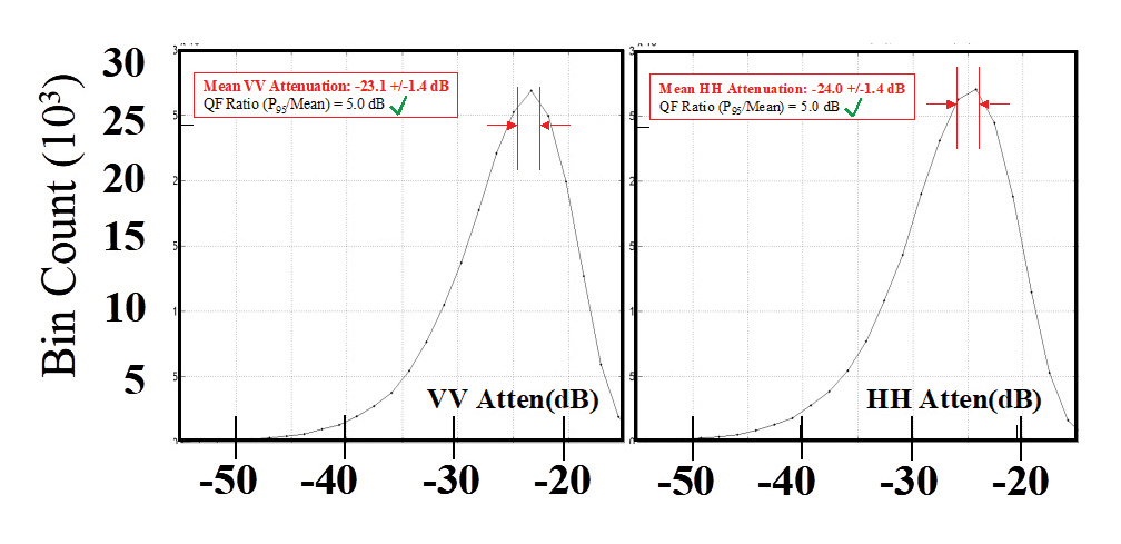
In the end, the aft bay EMI attenuation experiment was successful, and the corresponding C-band attenuation data is shown in Figure 21. This attenuation data was combined with a NASA susceptibility analysis. NASA determined that neither the NDR C-band or X-band radar waveforms would create any EMI/EMC disruption of critical Shuttle systems during ascent.
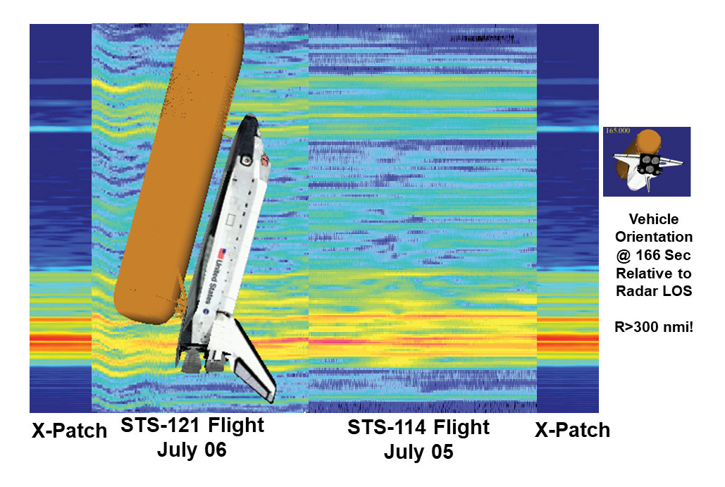
However, in order to train the radar operators, NASA needed a true C-band radar simulation of the Shuttle fly-out. This meant calculating the scattered field and RCS of the entire Shuttle stack, properly oriented in space and time relative to the NCAR site. The model had to include the period before SRB staging, SRB staging, and after SRB staging.
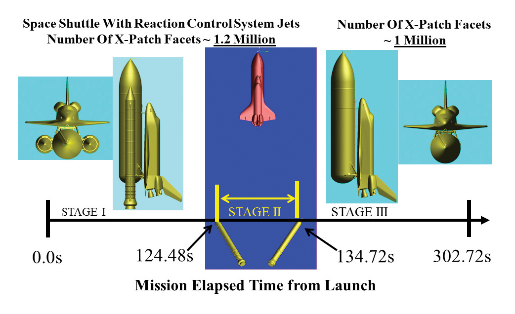
AFRL was again called to help, and through the technical leadership of Drs. Kueichien Hill and Tri Van, a viable solution was found. First, Hill and Van created an extremely detailed geometric grid of the entire Shuttle stack. NASA then provided three precise Shuttle-to-ISS fly-out launch trajectories over the five-minute launch window. The geometric grid was then coded into a physical optics-ray tracing RCS code called “X-Patch” and run on the U.S. Army’s best (2005 era) supercomputer.
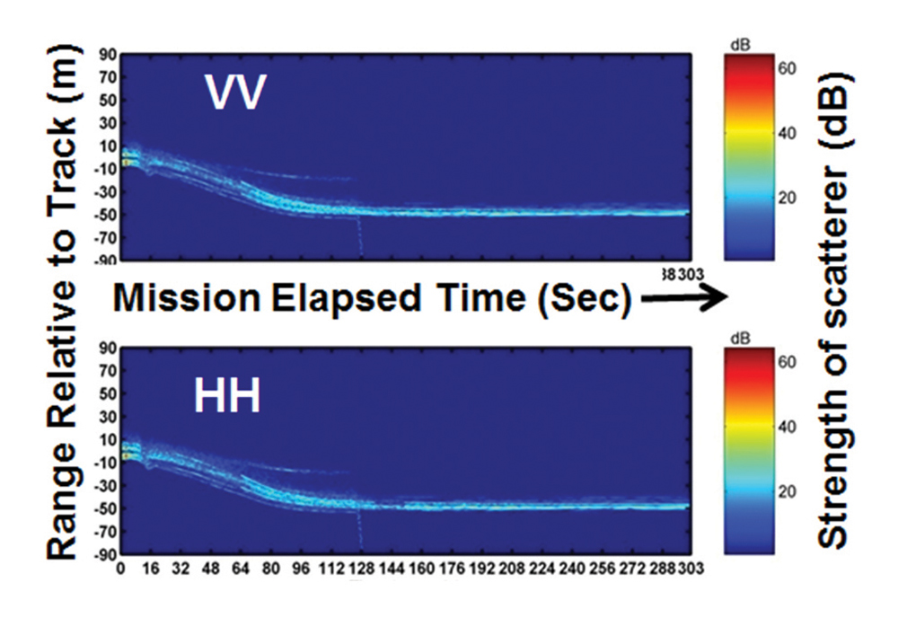
The Shuttle geometry had over 1.2 million facets. The RCS was calculated at 2048 frequencies, from 5.45-5.95 GHz, for every 1/3rd of a second, and for 302 seconds of mission elapsed time (MET). Given the three trajectories, the overall run-time was over two months of CPU time! The representation of the geometry is shown in Figure 22, and the constructed range-time intensity (RTI) data provided from X-patch is shown in Figure 23 on page 22.
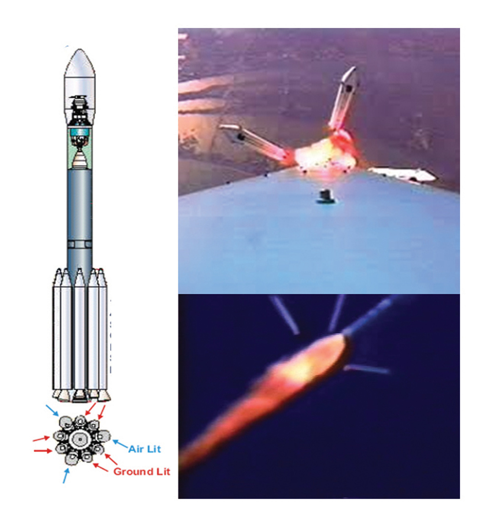
The most notable mission was the August 3, 2004 launch of a Delta-2 rocket carrying the NASA Mercury Messenger deep space probe. The Delta 2 was a great target to watch because it had nine strap-on solid rocket motor (SRM) boosters that used the same aluminum perchlorate propellant as the Shuttle SRBs. In addition, six of these boosters lit at lift off, burned for 60 seconds and were then ejected. The remaining three boosters then lit off, burned for another 60 seconds and were also ejected. In short, Delta-2 rockets generate lots of “normal debris” during a typical successful launch.
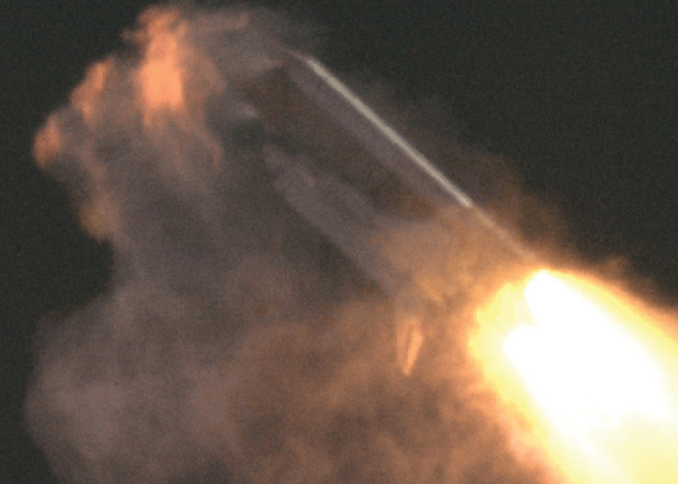
Figure 25 shows visual images of a daytime (not-Messenger) Delta 2 launch from an onboard and off-board camera, showing the moment of 3 air-ignited SRM’s separating from the Delta 2 at MET = ~120 seconds. The Messenger launch was at 2:00 am, so we had no such visual camera support, making the Messenger mission a perfect night launch dress rehearsal. The mission was successfully conducted, and the combined RTI and Doppler data processed overnight with clear and stunning results. During the period of six ground-lit SRM’s separating from MET 88-98 seconds, we saw very dim and low-level debris events, including particulate Al2O3 “slag” ejecting from the tumbling but spent SRM booster rockets. [10]
This mission was so crucial to RTF that the NDR team got an unexpected visit from the seven astronauts of the STS-114 crew the following afternoon after the Delta-2 mission. Based on this success and several other unmanned launches prior to July 2005, the NDR was approved for use on the very first RTF mission, STS-114 Discovery.
The powered flight mission lasts about 8.6 minutes, after which the NDR ground radar teams and photo teams go to work, pouring over all data to detect ascent debris events. NASA’s debris teams were especially concerned about any liberated debris that had a secondary collision with the orbiter itself. Radar could see such “ricochet” events as debris tracks that suddenly changed trajectory. In addition, we had installed trajectory overlay software that allowed a 3-dimensional Shuttle to be overlaid with range-time-intensity radar plots, as shown previously in Figure 24. The radar and photo teams had precisely 24 hours to report their findings to Mission Control in Houston.
In the meantime, once in orbit, the Shuttle deployed a second-tier inspection tool on the end of the payload bay boom to self-inspect its entire thermal protection system. Any inspection results would be correlated with the debris events recorded by the combined radar and optical debris teams. Lastly, as the Space Shuttle approached the ISS, the third tier required the Orbiter to perform a full pirouette tumble maneuver before docking, allowing ISS astronauts to photograph the entire Shuttle surface area at close range. This photographic data was also downloaded to a dedicated damage assessment team comprised of subject matter experts who assessed the health of the TPS to determine its adequacy for safe Shuttle re-entry.
At the conclusion of mission, and normally after undocking with the ISS, the Shuttle would again deploy their tier 2 inspection tool in orbit to assure themselves that the TPS system had not be struck by orbital debris during its time on orbit. If all systems showed no damage, the Shuttle would reenter the atmosphere and land. Of course, in the event anything was damaged beyond the ability to repair on orbit, The Shuttle would simply re-dock with the ISS and await a second Shuttle for the ride back to earth.
July 26, 2005 dawned warm and clear at the NCAR sight of the NDR radar system. Nearly a dozen radar technicians and data processing experts were awaiting the launch of Discovery at 10:49 EDT. The launch window was a very narrow 5 minutes long. The launch occurred right on time, and the NDR acquired the Shuttle shortly after it cleared the launch tower. We had excellent tracks for both the C and X band NDR radars, and data was acquired without a hitch.
Then the bedlam of data analysis started. To speed things up, we parsed the mission radar data with parallel teams working 20 second segments of the flight from launch to 450 seconds. The optical teams, working independently at first, were doing the same with nearly 50+ optical HD movie cameras. Our debris event report was due to Mission Control leadership within 24 hours of launch, and the clock was running!
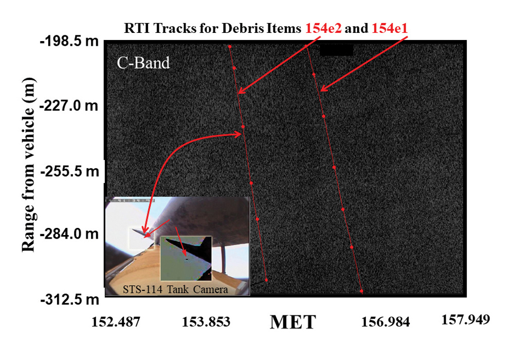
Almost immediately, we got our first challenging debris release. The external tank for the STS-114 return to flight system had been modified to remove much of the foam pieces that had a history of liberation in previous flights. But the first completely new tank design would not be delivered to NASA for three more flights, so everyone expected some foam debris events. One foam release was detected by the on-board external tank camera (inset of Figure 26) which raised immediate concerns. It was a very small piece of foam debris, a tiny fraction of the size of Columbia’s bipod ramp foam release. The camera clearly saw it depart and fly between the orbiter and tank, striking nothing. Despite its small size and very small corresponding RCS, the NDR not only detected this piece, but another smaller foam release the camera could not see. On its very first operational mission, the NDR proved that it could accomplish the debris detection and identification of material based on a combination of RCS, the location of the release, and its ballistic properties, Bn. So the ID strategy that effectively worked in the Columbia FD2 object investigation worked for Return to Flight ascent debris.
The Shuttle ultimately completed the ISS and was retired in 2011. As long as the ISS remains in operational service, NASA can proudly point to its completion in the Shuttle’s storied legacy. In the end, NASA recognized those responsible for the myriad of EM analysis, EMI/EMC, and RCS measurements whose backstory played a huge but unseen role in Shuttle’s return to flight.
- Columbia Accident Investigation Board Volume 1 (August 2003) and Volumes 2-6 (Oct 23, 2003).
- https://www.youtube.com/watch?v=aXiZ3RHR3bg
- https://bringingcolumbiahome.wordpress.com/2017/06/30/the-smoking-gun
- Kent, BM. Hill, K.C., Gulick, J., Van, T., An Assessment of Potential Material Candidates for the “Flight Day 2” Radar Object Observed During the NASA Mission STS-107 (Columbia), Air Force Research Laboratory Tech Note AFRL-SNS-2003-001, 20 Jul 03.
- Hill, K.C., Gulick, J., Kent, B, Van, T., “RCS analysis of the reinforced carbon-carbon tee-seals as potential ‘Flight Day Two’ candidates in support of the CAIB,” IEEE APS Symposium, 20-25 June 2004.
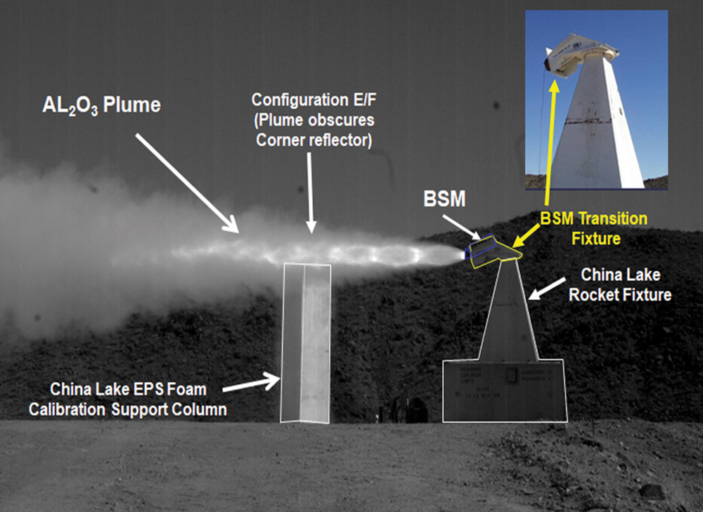
- Kent, B.M., Freundl, K., Griffith, A.D., “Mobile Diagnostic Laboratory Measurements of Transient Scattering Characteristics of a NASA Shuttle Booster Separation Motor (BSM) Plume,” Antenna Measurement Techniques Association 17-22 Oct. 2004 Technical Symposium, Atlanta, GA.
- Kent, B.M., Freundl, K., Griffith, Anthony D., “Mobile Diagnostic Laboratory Measurements of Transient Scattering Characteristics of a NASA Shuttle Booster Separation Motor Plume,” Antenna Measurement Technique Association 2004 Symposium Digest, 18-21 October 2004, Atlanta, GA, pp 12-17.
- Kent, Brian M.; Freundl, Kyle; Watkins, John; Coveyou, Thomas; Buterbaugh, Alan; Cravens, Lisa; Aft Bay Radar Frequency Attenuation Measurements of the Space Shuttle Orbiter OV-103 (Discovery), Air Force Research Laboratory (AFRL/SNS) Report TM-05-MDL-01, 17-Feb-2005.
- Kent, B.M., Watkins, J. Freundl, K., Coveyou, T., Cravens, L., Buterbaugh, A., Griffith, A., Scully, R. “Electromagnetic Interference Attenuation Test of the Space Shuttle Discovery using the Air Force Research Laboratory Mobile Diagnostic Laboratory,” Antenna Measurements Technique Association Symposium, 30 Oct-4 Nov 2005, Newport RI.
- Fletcher, Ed., Dalquist, C., “Support of NASA Delta II Messenger Launch to Mercury Missile Debris Monitoring Proof of-Concept Test, 3 August, 2004,” Missile Defense Division XonTech Systems Los Angeles, CA 10 Aug 2004, Rep. 04-0871.
- NASA frame capture from https://www.Space.com, posted on https://www.youtube.com/watch?v=21-mn3Mhdhs.