EMC concepts explained
Common-Impedance Coupling
Impact of the Return Path Impedance and the Return Current Levels
T
his month we explore the impact of the return path impedance and the return current level on common-impedance coupling between circuits. The measurements presented here were performed on a custom PCB containing audio, video, and high-current circuitry, where the return paths for each circuit were selectively shared with other circuits. This topic had been previously discussed in [1], where the measurements were taken with a first-generation PCB. The PCB has since been redesigned to lend itself to future modifications and to contain off-the-shelf, readily available components.
1. Common-Impedance Circuit Model
Consider the situation shown in Figure 1, where two circuits share the return path with a non-zero impedance.

Figure 1: Common-impedance coupling circuit
The voltages at the loads are

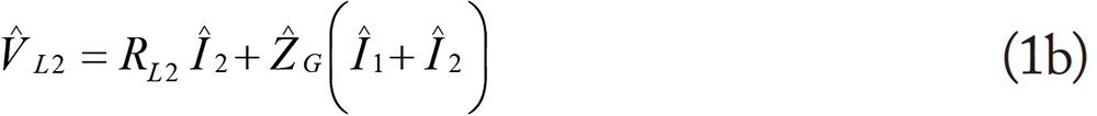
Note that the load voltage of circuit 1,  L1, is affected by the return current of circuit 2,
  L2; similarly, the load voltage of circuit 2, L2, is affected by the return current of circuit 1, L1. This type of coupling is called the common-impedance coupling. Common-impedance coupling becomes an EMC problem when two or more circuits share a common return path (common ground) and one or more of the following conditions exist:
L1, is affected by the return current of circuit 2, L2; similarly, the load voltage of circuit 2, L2, is affected by the return current of circuit 1, L1. This type of coupling is called the common-impedance coupling. Common-impedance coupling becomes an EMC problem when two or more circuits share a common return path (common ground) and one or more of the following conditions exist:- a high-impedance ground (at high frequency: too much inductance; at low frequency: too much resistance),
- a large ground current,
- a very sensitive, low-noise margin circuit, sharing the ground with other circuits.
(Note: a similar situation occurs when the circuits share a common forward path).
2. Measurement Setup and PCB Circuitry
Figure 2 shows the board used in the experiment, while Figure 3 shows the setup for the common-impedance measurements. The corresponding circuit diagram is shown in Figure 4. Figure 4 shows four different circuits and several switches controlling the return path for each circuit.

Figure 2: PCB board used in the experiment
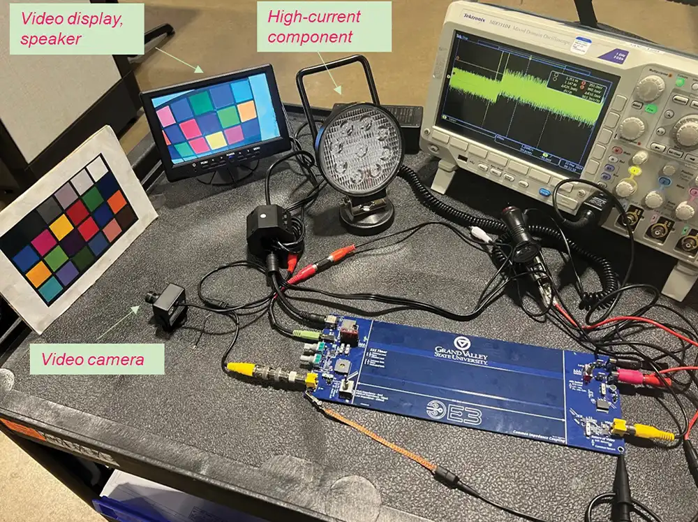
Figure 3: Measurement set up for common-impedance coupling
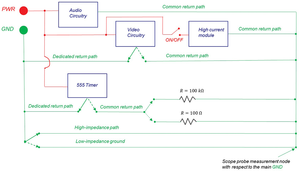
Figure 4: Circuit diagram
3. Measurement Results
First, we investigated the impact of the return path impedance on the audio circuitry with no other circuit sharing that path. This configuration is shown in Figure 5.

Figure 5: Audio circuitry: low- vs. high-impedance return path
Common-impedance coupling does not occur here, since there are no other circuits that could couple to the audio circuit. The measurement result is shown in Figure 6.

Figure 6: Audio circuitry measurement results: low- vs. high-impedance return path
In all measurements, cursor a shows the voltage levels for the low-impedance path, while cursor b shows the results for the high-impedance return path. There is an 18 mV voltage shift when changing from low to high impedance, with an audible increase in the speaker noise and slight video degradation.
Next, the video circuitry and the 555 timer currents were added to the common return path, shown in Figure 7.

Figure 7: Audio, video, and 555 circuitry (R = 100 kΩ): low- vs. high-impedance return path
There was no discernible impact on the audio and video circuitry. Subsequently, the current level from the 555 timer was increased by a factor of 1000 by changing the resistance value from 100 kΩ to 100 Ω in the return path, shown in Figure 8.
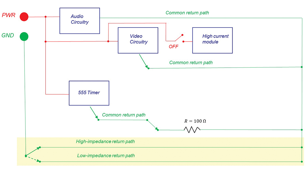
Figure 8: Audio, video, and 555 circuitry (R = 100 Ω): low- vs. high-impedance return path
The voltage shift between the low- and high‑impedance paths was 78 mV, shown in Figure 9. The audible speaker noise increased with additional video degradation.

Figure 9: Audio, video, and 555 circuitry (R = 100 kΩ): low- vs. high-impedance return path
Figure 10 shows the final system configuration, where a high current was injected into the common return path. The measurement result is shown in Figure 11.
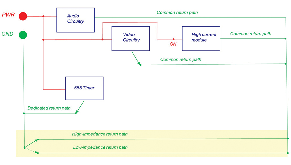
Figure 10: System configuration with the high current addition

Figure 11: Measurement results with the high current addition
Note the significant increase in the voltage levels (610 mV) compared to the previous cases. Both the audible speaker noise and the video degradation increased considerably. The measurements and observations support the conclusions presented at the end of Section 1.
References
- Adamczyk, B. and Teune, J., “Common‑Impedance Coupling between Circuits,” In Compliance Magazine, January 2018.
Share this story:

Dr. Bogdan Adamczyk is professor and director of the EMC Center at Grand Valley State University (http://www.gvsu.edu/emccenter) where he performs EMC educational research and regularly teaches EM/EMC courses and EMC certificate courses for industry. He is an iNARTE-certified EMC Master Design Engineer. He is the author of two textbooks, “Foundations of Electromagnetic Compatibility with Practical Applications” (Wiley, 2017) and “Principles of Electromagnetic Compatibility: Laboratory Exercises and Lectures” (Wiley, 2024). He has been writing “EMC Concepts Explained” monthly since January 2017. He can be reached at adamczyb@gvsu.edu.

Nick Koeller is an EMC Engineer at E3 Compliance which specializes in EMC & SIPI design, simulation, pre-compliance testing and diagnostics. He received his B.S.E in Electrical Engineering from Grand Valley State University, and is currently pursuing his M.S.E in Electrical and Computer Engineering at GVSU. Nick participates in the industrial collaboration with GVSU at the EMC Center. He can be reached at nick@e3compliance.com