hen I first started working as an independent EMC consultant, I didn’t have nearly half of the equipment I do now. The first piece of equipment I owned was a Siglent swept-type spectrum analyzer, and I made my own near-field probes and RF current probes following Ken Wyatt’s book [1].
I remember a case in which I needed to troubleshoot an immunity issue, but I didn’t have any equipment to inject noise into the system. At the time, I called my mentor, Keith Armstrong, and asked him if there was any way to solve the problem, given the limited kit I had. He said to me, “Have you heard about the reciprocity theorem?”
Here, I quote Henry Ott’s explanation in his book [2]:
I sat down and analyzed the noise sources in the environment. Having never been to the site where the issue was reported, my options were quite limited. I could only guess the spectrum the noise predominantly occupied, but the client also mentioned that the issue was only found recently.
For the past few years, the unit had been functioning well and without problems. They also mentioned that the most recent change in the environment was the addition of a LoRa communication link. A quick search on Google showed that LoRa operates at 863‑870/873 MHz in Europe.
So, my first attempt was to use my Tekbox TBDA3B, connect a near-field probe to the output of the amplifier, and inject 800-900 MHz RF power into the printed circuit board. I could also inject noise into the ribbon cable connection between the two boards. The TBDA3B has an output power of 40 dBmW (equivalent to 10 Watts). The field intensity of the near-field probe can be very high. To inject current into the ribbon cable, I used a BCI probe. The current injected into the ribbon cable via magnetic field coupling can reach tens of mA. However, I could not reproduce the same failure mode as the manufacturer saw in that particular location.
Here’s the question: How confident are we that it is 800-900 MHz causing the issue? Could it be some other frequency band?
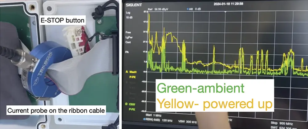
To find out, I recalled the reciprocity theorem and wondered if performing an emission measurement by placing an RF current probe on the ribbon cable would provide some good indication. Figure 1 shows an RF current probe clamped on the ribbon cable and the measurement results.
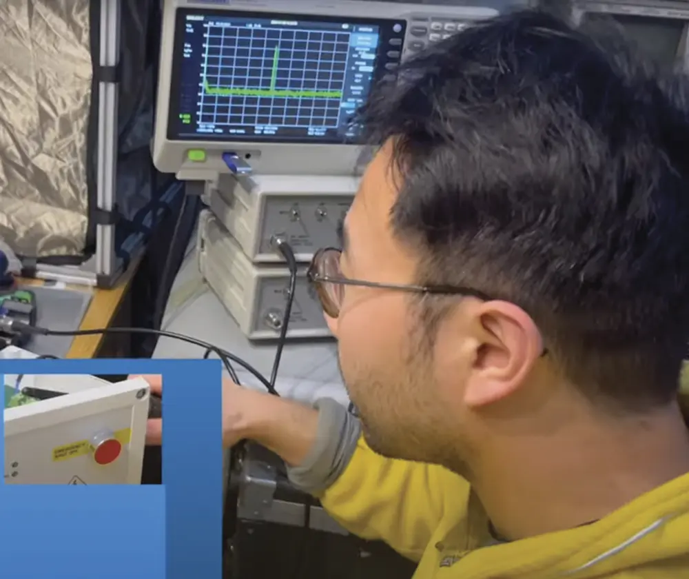
A quick injection using my walkie-talkie triggered the emergency stop, and the coupling path was identified as either the ribbon cable or the wire link between the emergency stop button and the PCB. Once this was identified, a flat ferrite core on the ribbon cable solved the problem.
Most walkie-talkies have an RF power rating of 1W, although some can operate at up to 4W or higher. This makes a walkie-talkie an excellent tool for injecting noise. By simply pressing the send button and moving the antenna around a PCB, you can introduce exposed RF noise into the circuit under test[1]. If the antenna runs parallel to a cable in close proximity, strong near-field coupling can occur, inducing RF current in the cable and affecting the unit.
Another valuable application is placing the walkie‑talkie antenna in parallel with the seams or apertures of a metal enclosure. If the enclosure’s shielding is not properly done, the field generated from the walkie-talkie may upset the unit.
- The actual field strength that is being developed at the EUT is unknown; depending on the output power of the walkie-talkie, this could be very high,
- Repeatable results are difficult to achieve, and
- Spot frequency tests may well miss resonances in susceptibility that will appear in the compliance test.
- Ken Wyatt, Create Your Own EMC Troubleshooting Kit (Volume 1) 2nd Edition: Essential Tools for EMC Troubleshooting (EMC Troubleshooting Trilogy).
