ince the advent of compact antenna test ranges and, somewhat more recently, near-field antenna test ranges, the number of newly built indoor test facilities has far surpassed the number of outdoor test facilities that have been constructed. Outdoor far-field testing requires suitable real estate, is subject to interference from external transmissions, and requires favorable weather conditions. However, the measurement of very large or very low-frequency antennas sometimes precludes a suitable indoor configuration.
While the antenna measurement methodology for outdoor far-field direct illumination ranges is well established, and there are several references to estimates of specific uncertainty terms [1]-[3], there are no comprehensive recommended practices for the estimation of measurement uncertainty. This is in contrast to the existing recommended practices for near-field [4] and compact antenna range measurements [5].
In this article, we identify key uncertainty terms for an outdoor elevated far-field antenna range and present a procedural methodology for predicting and evaluating the measure of uncertainty. The method for analyzing each term is described in detail in accordance with [6], commonly referred to as the Guide to the Expression of Uncertainty in Measurement (GUM). We then accumulated all uncertainty terms into a single value and present example uncertainty budgets for the antenna’s peak gain and -30 dB sidelobe measurements.
Shown in Figure 2 is the AUT positioner stack‑up configured as roll/slide/azimuth/elevation. It allows full polarization control of the AUT as well as translation along the z-axis. The conventional spherical coordinates are used to define the AUT coordinate system, also depicted in Figure 2. Here, the z-axis is defined as perpendicular to the AUT aperture plane, which may or may not coincide with the antenna’s electrical boresight.

The gain of the AUT is determined using the gain substitution method, where a gain standard antenna with a known gain value (in this case, a calibrated standard gain horn) is used to determine the absolute gain of the AUT. The standard gain horn had previously been calibrated by the manufacturer in a compact antenna test range and had been issued a certificate of calibration.
The source polarization purity term can be estimated using the following equation [2]:
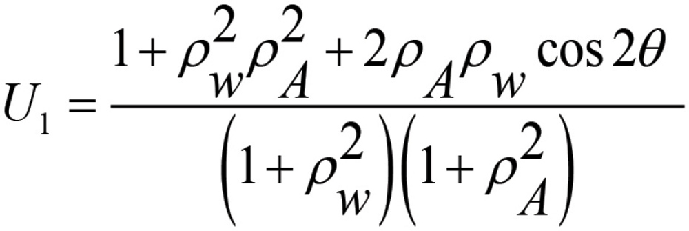
Here rw is the axial ratio of the transmitting antenna, rA is the axial ratio of the receiving antenna, and θ is the angle between the source and receiving polarization vectors. Assuming an ideal linearly polarized standard gain antenna (SGH), a purely circularly polarized AUT, and a Tx antenna axial ratio of 30 dB, the gain uncertainty can be estimated as ±0.279 / √3 = ±0.161 dB.
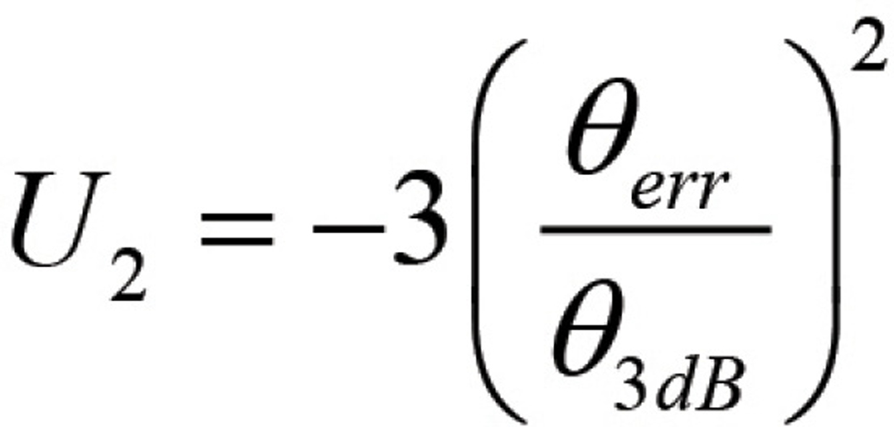
Assuming a standard positioner accuracy of 0.03 degrees and an AUT 3 dB beamwidth of 2.5 degrees, the estimated error for this term is approximately ±0.0004 dB and is, therefore, negligible.
- 3-antenna extrapolation ranges (~±0.1 dB)
- 3-antenna ranges without extrapolation (~±0.25 dB)
- Substitution method (~±0.5 dB)
The associated uncertainty is estimated by taking ten measurements of the peak of the beam RF signal after de-mating and then mating the cable to the AUT. The standard deviation of the measured signal is the estimate of the gain uncertainty, which we determined to be U4= ±0.058 dB.


 is the wavelength of operation. At 7.5 GHz, with a range length of 1086 m, the stray signal level due to inductive coupling on the considered outdoor far-field range can be estimated at -105 dB and can, therefore, be ignored.
The normal error allocated for this problem is 0.05 dB, meaning that the ratio of the re-radiated signal at the receiving antenna to the original signal should be at least -45 dB. Reference [2] derives the equation for the ratio of the power seen by the AUT from the re‑radiated signal from the source antenna to the original power transmitted by the source antenna when both are parabolic reflectors as:
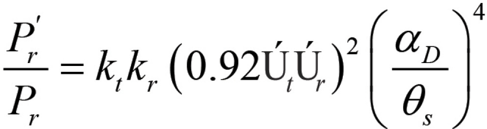
P’r = re-radiated power seen by the receiving antenna
Pr = desired power seen by the receiving antenna
kt = linear value of the reflected signal at the transmit antenna (for example, a return loss of 6 dB is a linear k = 0.25)
kr = linear value of the reflected signal at the receive antenna (for example, a return loss of 6 dB is a linear k = 0.25)
Út = efficiency of the transmit antenna = 0.5 (assumed)
Úr = efficiency of the receive antenna = 0.5 (assumed)
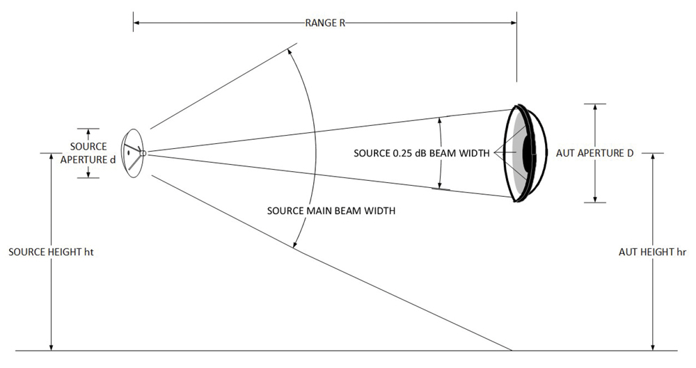
αD = the angle subtended at the source antenna by the aperture of the AUT
θs = the HPBW of the source antenna
Assuming a 3-degree HPBW for the source antenna, an AUT diameter of 1.2 meters, and antenna efficiencies of 50%, the equivalent stray signal is -92 dB, and, therefore, negligible. The calculation of the coupling term for the gain standard will result in similarly negligible values.
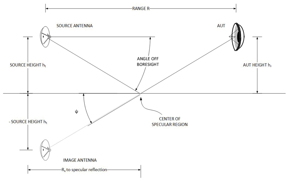

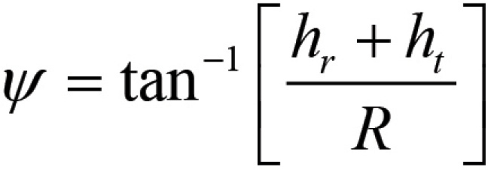
The range from the source to the center of the specular region is:

While the above analysis gives a useful approximation of the level of uncertainty due to reflections, the real outdoor range surface is far more complicated than the model. There are likely to be several points of reflection that will contribute to the error, along with several types of ground surface. Therefore, we use measurement to establish the reflection contribution.
The example range is equipped with an offset slide along the AUT z-axis. We took measurements as a function of slide position and recorded the maximum to minimum variation of the signal in the quiet zone. Finally, the maximum deviation from the RMS value of the measurement set is used to estimate the error due to reflections. The uncertainty in AUT gain is estimated to be U13 = ±0.033 dB, while the uncertainty in the -30 dB sidelobe level is estimated to be ±1.127 dB. When repeated for the gain standard, the measurement set resulted in a gain uncertainty of U6 = ±0.08 dB and has no effect on the sidelobe levels.
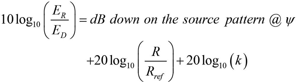
The estimated uncertainty may be obtained by evaluating the following equation [10]:

The receiver we used in the example test campaign was an MI-750 Advanced Digital Receiver with a stated amplitude linearity of 0.05 dB/10 dB. The effect on the gain uncertainty is assumed to be near zero, while the effect on the -30 dB sidelobe level measurement accuracy can be calculated as (0.05 ⋅ 3) /√3 = ±0.157 dB.
Similar to the receiver amplitude linearity, errors for this term tend to be negligible on the peak of the AUT beam and more significant on the sidelobe measurement accuracy. In practice, the RF subsystem dynamic range can be determined by measuring the signal level at the AUT peak of beam, disconnecting the source antenna, and terminating the cable with a 50 Ω load, and comparing the difference between the two signals. The dynamic range was found to be 107.5 dB and, therefore, has almost no impact on the gain uncertainty and only ±0.02 dB on the -30 dB sidelobe levels.
The most direct way of estimating this quantity is to compare the far-fields of two or more azimuthal scans taken with the exact same scan parameters. Preferably, five or more repeat measurements are performed without any change in the measurement system. The far-field patterns of the repeat measurements are then averaged, and the average is compared to a single measurement by complex plot subtraction. The pattern comparison and the RMS level are then used to determine the estimated uncertainty [7].
In Figure 5, we show the average of five azimuthal cuts, the first of the five patterns, and the pattern subtraction between them. From the RMS of the pattern subtraction, we estimate error contributions to the gain uncertainty and -30 dB sidelobe levels to be U15 = ±0.032 dB and ±0.973 dB, respectively.


- Newell, A.C., “Error analysis techniques for planar near-field measurements,” IEEE Transactions on Antennas and Propagation, Vol. AP-36, pp. 755-768, June 1988.
- Hollis et al., Microwave Antenna Measurements, Scientific-Atlanta, 1970.
- A. W. Moeller, “The Effect of Ground Reflections on Antenna Test Range Measurements,” The Microwave Journal, 1966.
- IEEE Standard 1720-2012, Recommended Practices or Near-Field Antenna Measurements.
- IEEE Standard 149-2021, Recommended Practice for Antenna Measurements.
- Guide to the Expression of Uncertainty in Measurement, BIPM, JCGM 100:2008, First Edition, September 2008.
- C. Parini, S. Gregson, J. McCormick and D. Janse van Rensburg, Theory and Practice of Modern Antenna Range Measurements, The Institution of Engineering and Technology, 2014.
- J. H. Hansen, J. Hald, F. Jensen and L. F. H., Spherical Near-field Antenna Measurements, The Institution of Engineering and Technology, 1988.
- S. Blalock and J. A. Fordham, “Estimating Measurement Uncertainties in Compact Range Antenna Measurements,” AMTA Symposium, 2015.
- J. McLaughlin and R. Shoulders, “Calibration of Mismatch Errors in Antenna Gain Measurements,” AMTA Symposium, 1992.
- D. Carpenter, “A further demystification of the U-shaped probability distribution,” International Symposium on Electromagnetic Compatibility, 2005.


Ned was a Senior Applications Engineer for NSI-MI Technologies. Ned’s thesis title for his Doctorate was “Terahertz Generation in Submicron Nitride-based Semiconductor Devices.” Much of the work in his career was spent in antenna design, development, and characterization of antenna performance. In addition to his thesis, Ned was the author or co‑author of 9 journal articles and 14 conference papers and presentations.
He was our colleague, friend, and family member. He will be greatly missed.
NSI-MI Technologies