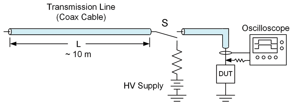
In the subsequent discussion all coaxial cables are assumed to be 50-ohm cables. It is also important to note that since TLP measurements have both high voltages and currents, it is important to incorporate appropriate attenuators at oscilloscope inputs to prevent damage. For simplicity, these attenuators are not shown. In all figures, current sensors are depicted by an oval around the center conductor and voltage probes are depicted by an arrow with a sense resistor. Connections to the oscilloscope are assumed to be 50-ohm coaxial cables.
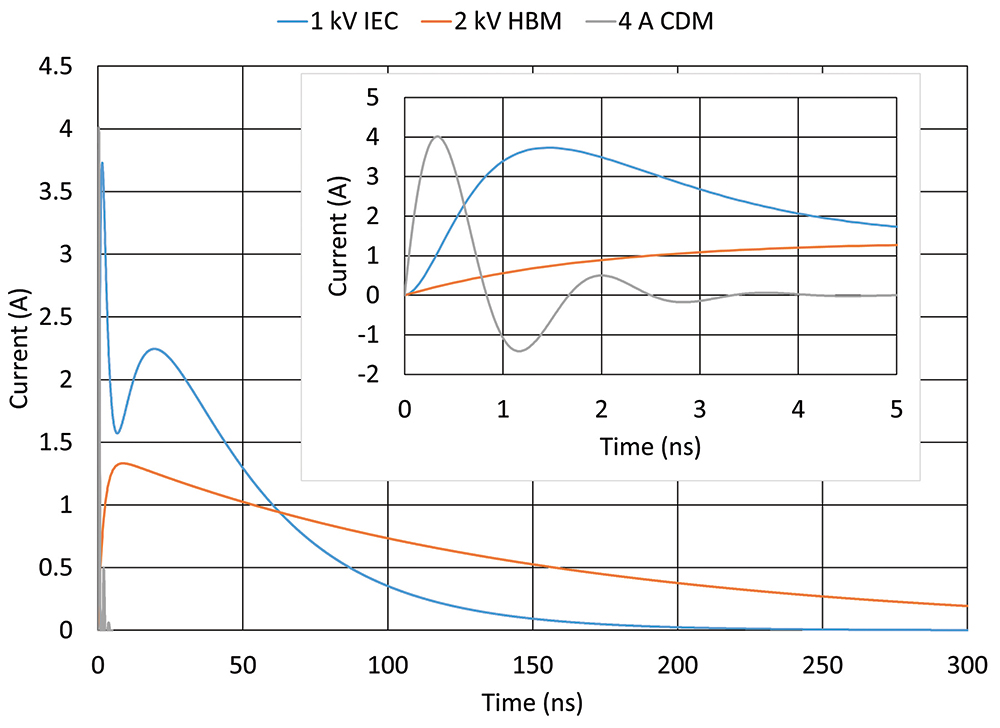
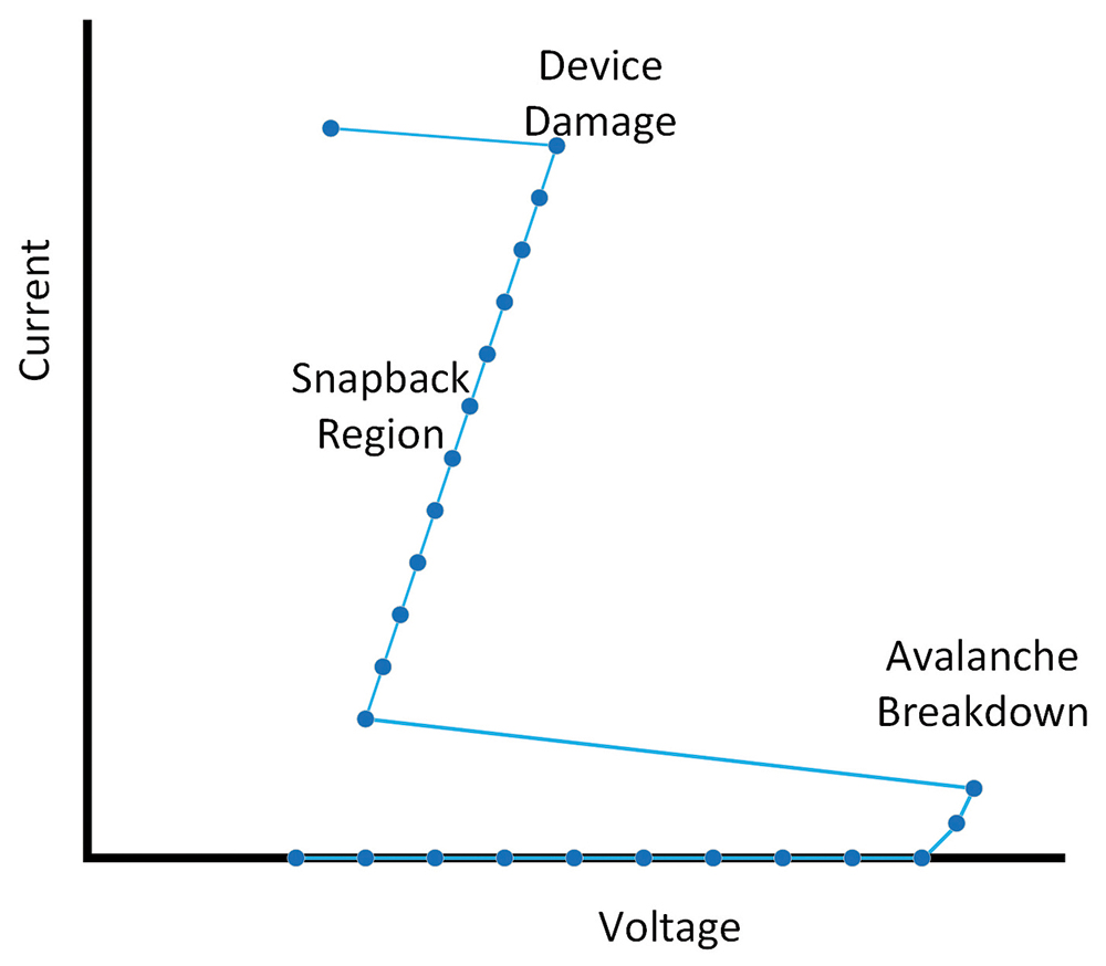
Other factors result in a proliferation of TLP types. TLP systems are high speed systems requiring signal paths that maintain a constant impedance except for the DUT itself. The challenges of high-speed measurements are especially true for pulse lengths below 10 ns, to the extent that such systems get their own name, very fast TLP (vf-TLP). The characteristic impedance of the TLP system can also affect the resultant measurement, potentially hiding important characteristics of the DUT. To explore the challenges and solutions in TLP measurements, several TLP variations will be discussed, time domain reflection in this article and several other configurations in Part 2.
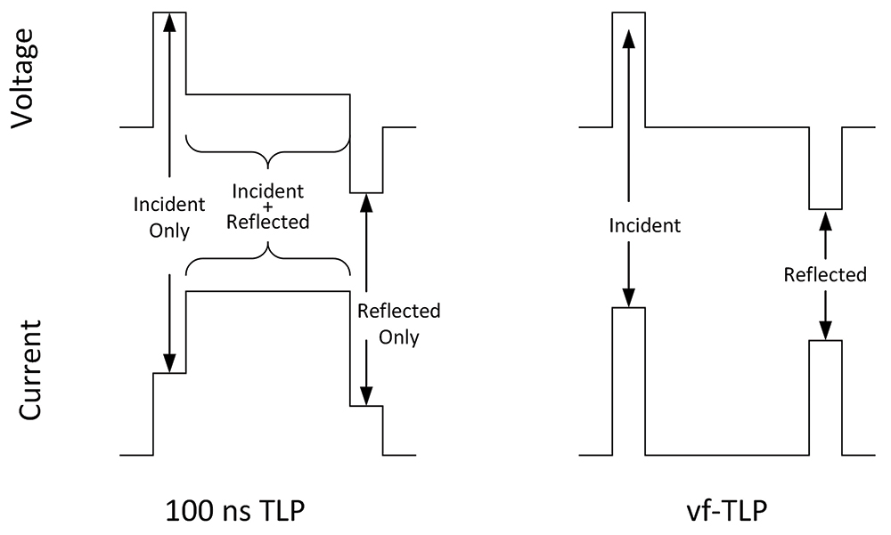
In TLP systems the voltage and current probes are often placed some distance from the DUT. This is done because it is often easier to maintain a constant impedance at the position of the probes at a position away from the DUT. This is especially true when doing wafer probing. To determine the voltage and current at the DUT, it is necessary to rely on the reflection properties of signals traveling in coaxial cables when they meet a change in impedance. These properties are described by the following equations, where VI and II are the incident voltage and current, VR and IR are the reflected voltage and current, and ZCable and ZDUT are the cable and DUT impedances.

This cannot be done with vf-TLP because the pulse length is too short for there to be sufficient, or any, overlap at the probes of the incident and reflected signals. For vf-TLP it is necessary to have the probes and DUT sufficiently separated that the pulses have no overlap. The digital data from the oscilloscope is used to time shift the incident and reflected pulses numerically and then add them together to obtain the voltage and current experienced by the DUT. An advantage of the vf-TLP method is that the time dependence of the voltage and current can be observed directly in the added signals. The disadvantage is that vf-TLP I-V curves are often much noisier than for 100 ns TLP. This is because for a low resistance DUT the vf-TLP voltage measurement is the subtraction of two large numbers while the 100 ns TLP is a direct measurement. In vf-TLP care must also be taken to obtain the proper amount of time shift when adding the incident and reflected signals or critical time dependent features can be distorted.
The above discussion for TDR TLP implies that the 100 ns TLP and vf-TLP measurement systems are the same except for the length of the charged cable which determines pulse length. This is true in principle but usually not in practice. Measuring I-V curves with 100 ns TLP is relatively forgiving of less-than-ideal test fixturing. Short clip leads and standard wafer probes can be used to connect from the coax pulse source to the DUT. The voltage probe can be a standard 500 MHz oscilloscope probe and the current probe can be a Tektronix CT1 probe in an appropriate fixture. This is not the case for vf-TLP, where maintaining 50-ohm impedance right up to the DUT is critical. For wafer level measurements, RF probes become a requirement. To obtain the required bandwidth for voltage measurements, voltage pickoff Tees with resistances between 1000 and 5000 ohms are used rather than oscilloscope voltage probes. For vf-TLP current measurements are often obtained from the voltage data using I = V/50 ohms due to bandwidth limitations of current probes. In 100 ns TLP with overlapping incident and reflected pulse, device current cannot be determined from the voltage measurement because the voltage does not contain the needed directional information for a current measurement. In vf-TLP with separated incident and reflected currents, the directional information is known.
- Martin, A. R., 2011a, “A new TIA standard for equipment installations with two or more separate grounds,” Alliance for Telecommunications Industry Solutions (ATIS) PEG Conference 2011, https://www.atis.org.
- Martin, A.R., “How Grounds Affect the Peak Voltage Due to Lightning,” In Compliance Magazine, April 2021, pp 37-40
- Grcev, L., “Impulse Efficiency of Ground Rods,” IEEE Transactions on Power Delivery, vol. 24, no. 1, January 2009, pp 441-451.
- Pretorius, P. H., “Was Lightning Ground Potential Rise Overlooked in the Design of Large Earth Electrodes?” EE Publishers, March 26, 2018.
- Tominaga, Tetsuya, “Damage to Equipment in Japan” ITU-T Study Group 05, Technical Session on Home Networks Geneva, 29/04/2011, https://www.itu.int/dms_pub/itu-t/oth/06/52/T06520000020001PPTE.ppt.
- Ardley, Tim, “Protecting PoE PSE and Ethernet to the latest international OSP standards,” The Alliance for Telecommunications Industries Solutions Protection Engineers Group, Monroe, LA, April 2016.
- Wiese, Jim, “Evolving Ethernet Applications Have Resulted in Protection Challenges,” The Alliance for Telecommunications Industries Solutions Protection Engineers Group, Littleton, CO, March 2014.
- Okugawa, Yuichiro, Honma, Yasuhiro, and Takaya, Kazuhiro, “EMC Technology that Protects Network Equipment from Electromagnetic Problems,” NTT Technical Review, March 2014, vol. 12, no. 3.


