EV Battery and BMS Testing in Validation and Production Scenarios

lectric vehicles are clearly a rapidly growing part of the automotive scene. They promise low or no emissions, conceivably low cost of energy from the power grid, yet they will continue to deliver us safely from here to there. However, electric vehicle design and manufacturing is clearly a paradigm shift for the automotive industry – new drive systems, technologies, and test plans.
Electric vehicles are bringing new test and validation challenges as the electronic and software content of the vehicles grow. In this article, we will discuss the basics of electric vehicle battery pack designs and some of the tests that should be performed on them in a manufacturing environment. We’ll also discuss a conceptual solution to this complex testing challenge.
Uncontrolled energy releases can be caused by severe physical abuse, such as crushing, puncturing, or burning, which can be mitigated by mechanical safety systems and proper physical design. However, they can also be caused by shorted cells, an abnormally high discharge rate, excessive heat buildup, overcharging, or constant recharging, which can weaken the battery. These causes are best prevented by a properly designed and validated electronic safety and monitoring system, better known as a battery management system (BMS).
One of the major validation and safety challenges to be tackled in modern EVs, HEVs, and PHEVs concerns the effective testing of the Battery Pack itself and the Battery Management Systems (BMS) – the complex electronic system that manages the performance and safety of the battery pack and the high levels of electrical energy stored within. In the sections below, we will describe both the battery pack and the BMS in greater detail.
The large stack of cells is typically grouped into smaller stacks called modules to assist in manufacturing and assembly. Several of these modules will be placed into a single battery pack. The cells are welded together within each module to complete the electrical path for current flow. Modules can also incorporate cooling mechanisms, temperature monitors, and other devices. In most cases, modules also allow for monitoring the voltage produced by each battery cell in the stack by the BMS.
The battery pack also contains relays, or contactors, which control the battery pack’s electrical power distribution to the output terminals. In most cases, there will be a minimum of two main relays that connect the battery cell stack to the pack’s main positive and negative output terminals, those supplying high current to the electrical drive motor. Some pack designs will include alternate current paths for pre-charging the drive system through a pre-charge resistor or for powering auxiliary busses with their associated control contactors. For obvious safety reasons these contactors are all normally open.
Collection of data from the pack sensors and activation of the pack relays are accomplished by the pack’s battery management system (BMS). The BMS is also responsible for communications with the world outside the battery pack and performing other key functions, as described in the following section.
In a nutshell, the BMS system must read voltages and temperatures from the cell stack and inputs from associated temperature, current, and voltage sensors. From there, the BMS must process the inputs, make logical decisions to control pack performance and safely, and report input status and operating state through a variety of analog, digital, and communication outputs.
The sub-modules and main module communicate on an internal data bus such as controller area network (CAN). Power for the BMS can be supplied by the battery stack itself or from an external primary battery such as a standard 12V lead acid battery. In some cases, the main module is powered externally, while the sub modules are powered parasitically from the battery modules to which they are attached.
For example, SoC information is critical to estimating and maintaining the pack’s usable lifetime. Usable battery life can be dramatically reduced by simply charging the pack too much or discharging it too deeply. The BMS must maintain the cells within safe operating limits. The SoC indication is also used to determine the end of the charging and discharging cycles.
To measure SoC the BMS must include a very accurate charge estimator. Since you can’t directly measure a battery’s charge, the SoC must be calculated from measured characteristics like voltage, temperature, current, and other proprietary (depending on the manufacturer) parameters. The BMS is the system responsible for these measurements and calculations.
When degraded cells with a diminished capacity exist within the battery stack, the performance of the pack as a whole is degraded. During the charging cycle, there is a danger that degraded cells would be subject to overcharging before the rest of the cells in the chain reach their full charge. As a result, temperature and pressure may build up and possibly damage that cell. The weakest cell will have the greatest depth of discharge during discharging and will tend to fail before the others. The voltage on the weaker cells could even become reversed as they become fully discharged before the rest of the cells resulting in the early failure of the cell.
Cell balancing is an active way of compensating for weaker cells by equalizing the charge on all the cells in the chain and thus extending the battery pack’s usable life. During cell balancing, circuits are enabled which can transfer charge selectively from neighboring cells, or the entire pack, to any undercharged cells detected in the stack.
To determine when active cell balancing should be triggered and which target cells, the BMS must be able to measure the voltage of each individual cell. Moreover, each cell must be equipped with an active balancing circuit.
SoH metrics can be as simple as monitoring and storing the battery’s history using parameters such as number of cycles, maximum and minimum voltages and temperatures, and maximum charging and discharging currents, which can be used for subsequent evaluation. This recorded history can be used to determine whether it has been subject to abuse, which can be an important tool in assessing warranty claims.
More advanced measures of battery SoH can include features such as automated measurement of the pack’s isolation resistance. In this case, specialized circuits inside the battery pack can measure the electrical isolation of the high current path from the battery pack ground planes. Such a safety system could preemptively alert the operator or maintenance technicians to potential exposure to high voltage.
CAN (controller area network) is the most common communications bus in automotive applications, although automotive ethernet, RS232 / RS485 serial, SPI, TCP/IP, or other networks could be used. CAN networks come in various implementations and can include a range of higher level “application layer” protocols like unified diagnostic services, OBD II, J1939, etc.
Aside from a digital bus, separate analog and/or digital inputs and outputs should be considered as supplemental parts of the BMS interface and communication. Discrete inputs and outputs can be used for redundancy and for operations requiring a separate interface such as activating an external contactor, fan, or dashboard lamp.
Accurately simulating all the conditions to which a BMS may be subjected during real world operation is not easy. However, one must consider the long-term cost of skipping testing over a full range of conditions, remembering that any given condition could lead to a critical failure in the field. In the end, simulating nearly every combination of cell voltages, temperatures, and currents you expect your BMS to encounter is really the only way to verify that your BMS reacts as you intended in order to keep your pack safe and reliable.
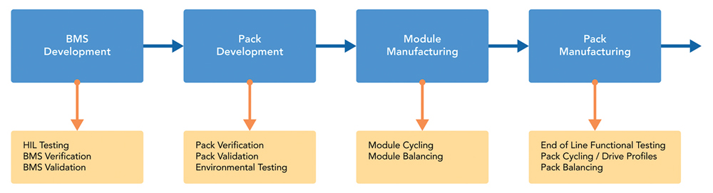
After EOL functional testing is completed, packs may also be subjected to charge/discharge cycling and drive profile cycling, which will simulate the typical conditions the pack will see when integrated into the EV drivetrain. Packs can also be run through active cell balancing routines to set each cell’s initial charge state to a nominal condition or set the Pack SoC to a level appropriate for shipping and storage.
When considering off-the-shelf systems for use in your test plan, make sure to ask yourself these three basic questions:
- Are you getting everything you need just the way you want it, or are you settling for what the other person needs?
- Are you using everything you will pay for, or are you paying for things you won’t use?
- Is it flexible enough to accommodate your future needs but not so flexible that it becomes cumbersome to use?
Choosing a modular hardware and software testing platform tailored to meet your requirements can be used to jump start this approach, making it a very viable option. This is especially true if the platform you choose leverages proven commercial technologies and open industry standards.
In the end, this modular platform-based testing approach can have several benefits:
- It can dramatically lower the cost of the test system, both in initial capital expenditure and overall cost of ownership, through the use of commercial technologies and standards.
- It can increase your test throughput with fast measurement hardware and software capable of managing multiple test routines in parallel.
- The time required to adapt such test systems for new products will decrease through the use of flexible, modular software and hardware.
- You can get exactly what you need, the way you want it. You can get everything you paid for and your test station will be flexible, without being cumbersome to use.
- The system is tailored to your product and workflows, resulting in a simplified user experience, shorter learning curve, and corresponding personnel time savings.
It is highly desirable to achieve standardization, cohesion, and efficiency of testing throughout the EV component product cycle and during inevitable future product evolution. It is best to take a platform-based approach to address this testing challenge to achieve this. This means establishing a unified suite of test equipment built on common reusable building blocks (both hardware and software) and utilizing various configurations of this platform to cover testing of battery cells, modules, packs across various testing regimes (R&D, validation, HIL, production, and lifecycle tests).
This requires incorporating reliable software and hardware architectures and flexible and reliable subsystem components, which can be customized to specific use cases and changing requirements. Utilizing high-quality COTS (commercial off-the-shelf) hardware assembled from best-in-class instrumentation vendors typically improves system performance, reliability, and maintainability while significantly reducing the engineering effort involved in deploying the system.


can be reached at jesse.batsche@dmcinfo.com.
can be reached at jesse.batsche@dmcinfo.com.