(radio frequency) field probes are an essential piece of equipment used for measuring the intensity of radiated RF fields. Although this instrument is crucial in implementing a radiation immunity test system, system specifiers often gloss over this essential element after spending a considerable amount of time and energy selecting amplifiers, antennas, and other equipment to generate the required RF field. A live test using a field probe will then determine if the RF test system’s expected performance has been achieved.
These specialized RF measuring instruments carry a unique set of specifications. Understanding the specification definitions, field probe design characteristics, and other varying features will, in turn, allow a confident and informed decision in choosing a suitable field probe.
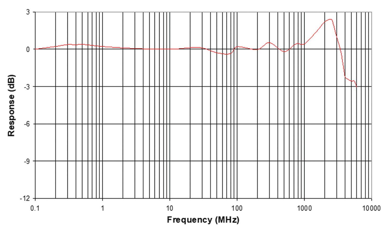
An example of a frequency response curve is shown in Figure 1. If the probe does not cover the entire frequency range of the test application, multiple probes may be required.
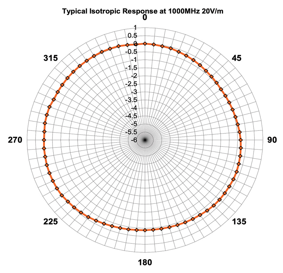
The graphic shown in Figure 2 on page 20 shows a typical isotropic response of a probe. If calibration factors were applied to each axis, the resultant curve would approach an ideal concentric circle or completely isotropic. The term isotropic gives the impression that measurements are taken as the probe is rotated in every direction. However, this is not the case due to the time this would take, and the resultant calibration cost. An example of an isotropic deviation is ±0.5 dB, 0.5 MHz – 2 GHz.
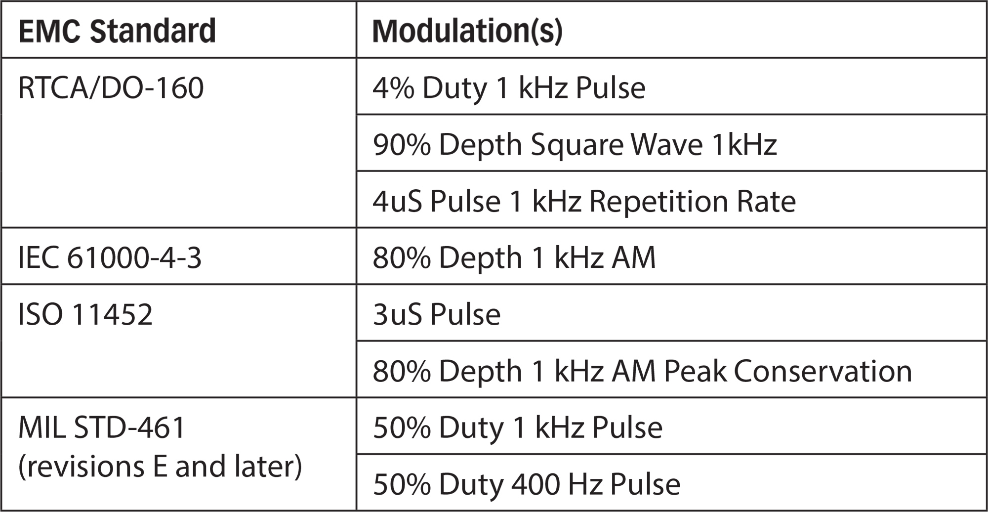
However, many EMC specifications use modulation in some form, primarily pulse modulation (PM) or amplitude modulation (AM). A CW-only field probe is not appropriate for measuring these signals, and an alternative type of probe needs to be selected based on the modulation being used.
The product specification sheet should be consulted to understand the probe’s capability. Some probes are limited to specific modulation types, while others will measure CW, PM, and AM fields. When deciding on a field probe for measuring modulated fields, ensure that the probe selected is appropriate for the modulation being used. A CW-only field probe will often produce values in a modulated field. However, the readings will likely be erratic and would not be usable for field measurements. Consult the test standard being used for guidance on appropriate probe selection.
Some older probe designs, classified as non-isotropic, use a single sensor, and can only detect a single field polarity. With this type, the probe must be carefully oriented, with respect to the field, to perform field measurements. Most EMC test standards require isotropic probes, precluding the use of non-isotropic models in these cases. Consult the test standard being used for guidance on appropriate probe selection.
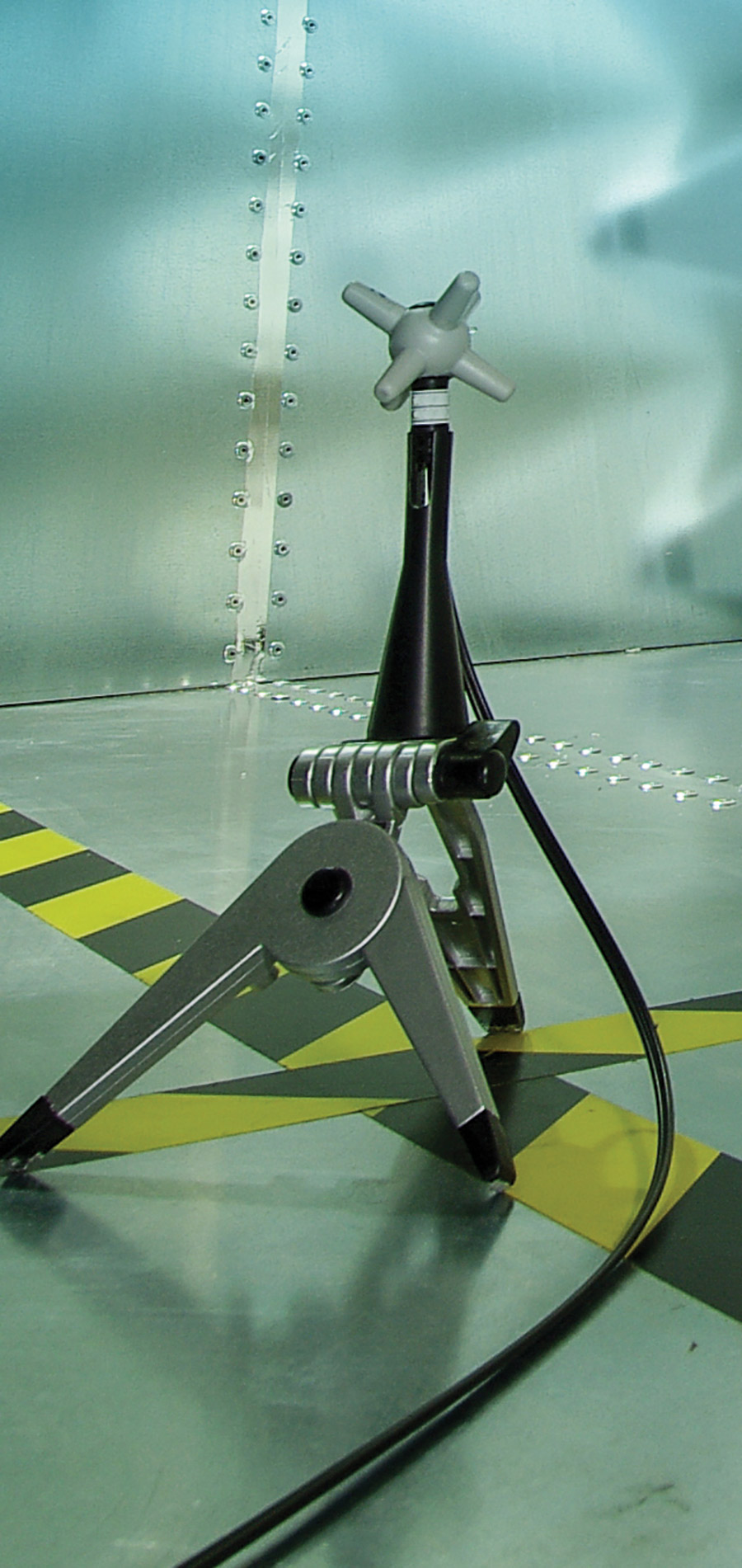
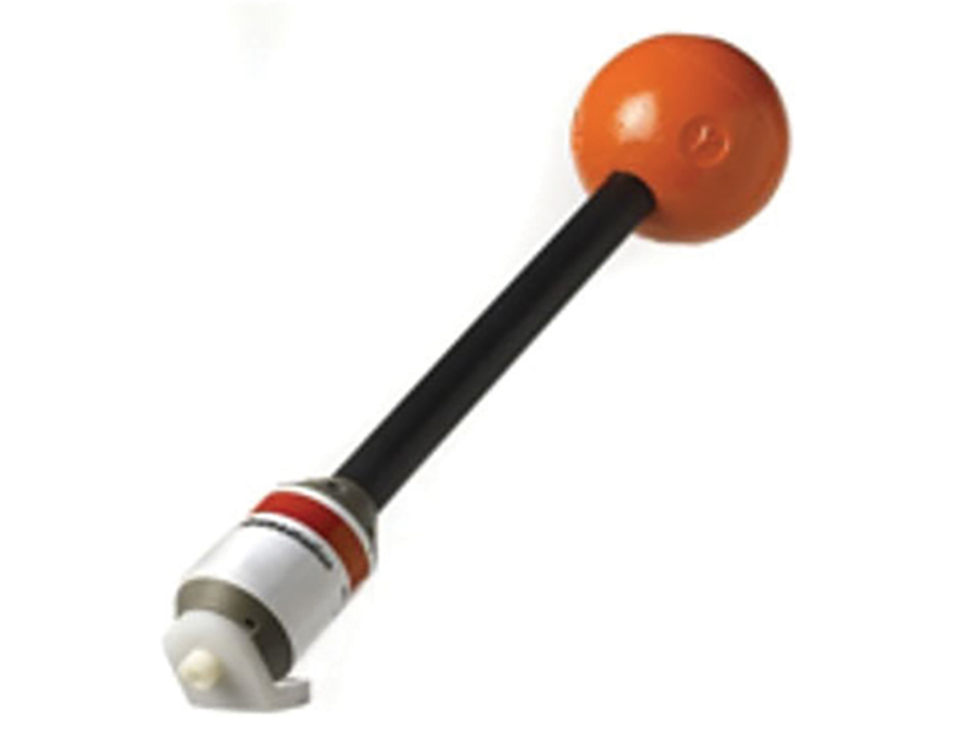
The stalk style presents as an antenna ball on a pole, or stalk, remote from the probe’s body, as shown in Figure 3.3. This configuration separates the RF sensors from the reflective electronic housing via a stalk, which provides performance benefits. Separating the sensor elements from the housing allows minimizing the size of the sensor elements (antennas) in the probe head, resulting in the ability to operate at higher frequencies while also reducing disturbance to the field being measured. Minimizing the housing/body size will also reduce the disruption of the field. While the stalk probe is an excellent approach, there may be limitations in usage due to the measurement location’s physical constraints.
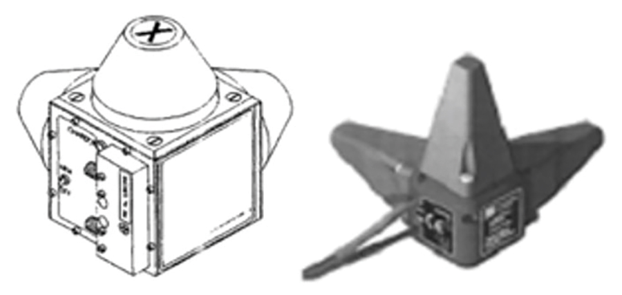
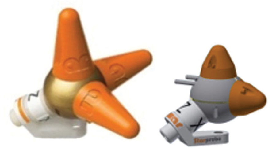
The monopole-over-ground plane style, seen in Figures 3.1 and 3.2, is typically seen as a metal cube or sphere, with three protruding orthogonal antenna elements. The cube or sphere body contains probe circuitry and acts as a ground plane for the antenna elements. The smaller overall physical size relative to the stalk probe may allow for use in applications where the stalk probe is too large.
Cube-style monopole-over-ground plane probes have a cubical-shaped body and come in various sizes. In general, the smaller the better since a small probe has less effect on the RF field resulting in improved performance.
An alternative sensor type is a thermocouple sensor. Thermocouple sensors can measure the average amplitude of a repetitive modulated field correctly; however, the modulation envelope would need to be known if a maximum reading was required. These sensors do not suffer from the same nonlinear response to modulated fields that diode type sensors do; however, thermocouple type sensors have a much slower response time than diode-based sensors. Since thermocouple probes are less sensitive and have a narrower dynamic range than diode-type probes, they are not commonly used in EMC immunity applications.
Battery-powered probes contain batteries in the probe housing. While battery-powered field probes and monitors are useful for hand-held mobile usage, the trade-off is reliability. Rechargeable batteries have a limited charge life as well as occasional failures. Since some probe vendors require that the probe be returned to the factory for battery replacement and recalibration, a simple battery failure can shut down an immunity test system. Running out of battery power in the middle of a test is also a limitation of battery-powered probes.
For applications that do not require the mobility provided by a battery-powered field probe, laser-powered probes have been designed to avoid the reliability issues encountered with rechargeable batteries. This power-over-fiber (PoF) system uses a high-energy laser driver to deliver laser energy to the probe via the same fiber optic cable used for communications. A converter within the probe converts the IR back to electricity to power the probe. Unlike a probe that relies on rechargeable batteries for power, a laser-powered probe can operate indefinitely, which translates to a vast improvement in reliability and productivity.
Laser safety must be considered whenever products are used that contain lasers. These products will fall into various categories dependent upon laser characteristics and power. Regardless, products containing lasers need to comply with safety standards that exist to protect the user. Product manufacturers must ensure their product design incorporates proper safety mechanisms and labeling to conform to the applicable safety standard requirements.
Since high field levels and even operating EUTs can generate a great deal of heat, it is difficult to actually determine the dynamic heat fluctuation at any given moment, much less apply the correction factor. Thus, this cumbersome chore is often ignored, which introduces a source of error. Some manufacturers provide probe models with internal temperature compensation that automatically adjusts as probe temperature changes. For these probes, as long as the probe is used within its stated parameters, no additional temperature compensation is necessary, removing a source of thermal measurement error.
Selecting the proper field probe with the appropriate characteristics and functionality is the first step toward performing RF field measurements. Once a probe is selected, using proper measuring techniques and best practices in operating the probe is important to achieve accurate measurements.