utomotive standards addressing electromagnetic compatibility (EMC) are developed mainly by CISPR, ISO, and SAE. CISPR and ISO are organizations that develop and maintain standards for use at the international level. SAE develops and maintains standards mainly for use in North America. In the past, SAE developed many EMC standards which were eventually submitted to CISPR and ISO for consideration as an international standard. As the SAE standards become international standards, the equivalent SAE standard is then withdrawn as a complete standard and reserved for use to document differences from the international standard.
Each vehicle manufacturer has internal corporate standards that specify the testing, severity, and sensitivity levels that components used in their vehicles, and the complete vehicle must meet. As with the government standards, these documents usually refer to the CISPR and ISO documents with differences in scope or test levels. In the past, a vehicle manufacturer based in the U.S. referenced SAE documents in their corporate standards, today most U.S.-based vehicle manufacturers market worldwide. Therefore, they reference CISPR and ISO standards in their internal corporate standard, and this is also true for other established and emerging manufacturers.
CISPR/D is responsible for developing and maintaining the standards used to measure the emissions produced by vehicles and their components. ISO/TC22/SC32/WG3 is responsible for developing and maintaining the standards used for immunity testing of vehicles and their components. ISO standards for the vehicle industry are mainly broken into two categories, vehicle (ISO 11451-xx) or component (ISO 11452-xx, ISO 7637-xx). Table 1 on page 10 provides an overview of the CISPR and ISO EMC standards for the automotive industry.
As with the ISO EMC standards, SAE EMC standards are mainly broken into two categories, vehicle (SAE J551-xx) and component (SAE J1113-xx). As can be seen in the notes of Table 1, many of the SAE standards are inactive because they have been withdrawn as complete standards and reserved for use to document differences from the international standards. Table 2 on page 12 does not show all the EMC standards related to automotive published by the SAE, but it gives an overview of the main standards and cross-references to the equivalent ISO or CISPR document. Table 2 shows the main SAE standards that are still active for both vehicle components and vehicles.
As with Table 1, Table 2 is not intended to show all the different parts of the standard, but to show the complexity of the standard documents and the many parts and methods that are covered under them. As mentioned above, government standards and directives in many cases refer to the CISPR or ISO methods. 2004/104/EC, which surpassed 95/54 EC, is a European directive for vehicle EMC. Its sections related to automotive components follow the directions given in the CISPR 25 document.
CISPR 36 radiated emissions measurements are made at 3-meter test distance with a loop antenna (although the limits are for the protection of off-board receivers at a distance ≥ 10 meters). The magnetic field emissions measurements are normally done on an OTS, open area test site (OATS), or in an ALSE. Site correlation/validation is currently not covered in CISPR 36. However, site validation is being considered as a work item for future editions.
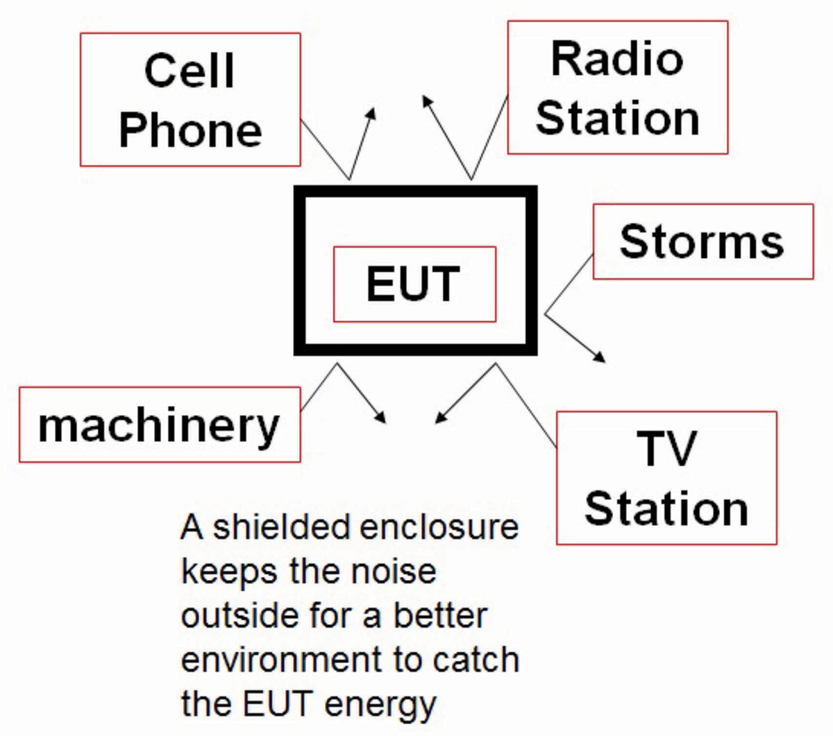
CISPR 25 states that the electromagnetic noise level in the test area has to be 6 dB lower than the lowest level being measured. Some of the radiated emissions limits found in CISPR 25 are as low as 18 dB (μV/m). This means that the ambient noise must be 12 dB (μV/m) maximum for a compliant environment. An RF-shielded room is typically used to keep RF signals from the external environment out of the test area so that the equipment under test (EUT) remains the dominant source of any radiated interference.
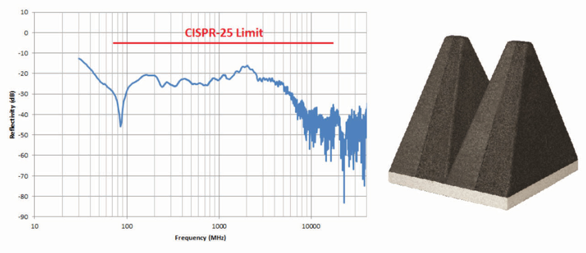
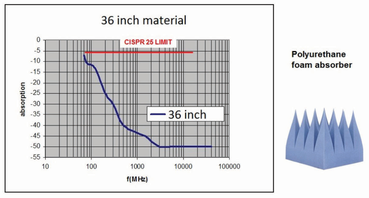
Although the shielded room is too small to support resonant modes at low frequencies, the number of modes increases with frequencies above the cut off of the chamber. When these resonant modes appear, they can add significant errors to the measurements. To reduce these errors, the shielded room covered with RF absorber material on its ceiling and interior walls greatly suppresses internal reflections so that the dominant coupling path is between the EUT and measurement antenna. By adding RF absorber to the walls and ceiling of the shielded room, the room becomes an absorber-lined shielded enclosure (ALSE). CISPR 25 in its current version (Ed 5:2021) covers a frequency range of 150 kHz to 5.95 GHz and to date absorber technology is unable to provide appreciable absorption at levels down in the 150 kHz range. One beneficial consequence of the low measurement frequency and the 1-meter measurement distance is the fact that the chamber sizes are electrically small at these low frequencies, so no significant resonant behavior appears. Therefore, the standard concentrates on absorber performance at 70 MHz and above. The standard requires that the absorber used must have better than -6 dB absorption at normal incidence. To achieve these levels, there are several types of absorber technology on the market today.
The layout and dimensions of the typical CISPR 25 ALSE is guided by the standard. Several guidelines must be followed when sizing the chamber and the starting point is the EUT, which determines the size of the test bench. Figure 5 shows a typical test bench used in a CISPR 25 and ISO 11452-2 type chamber.
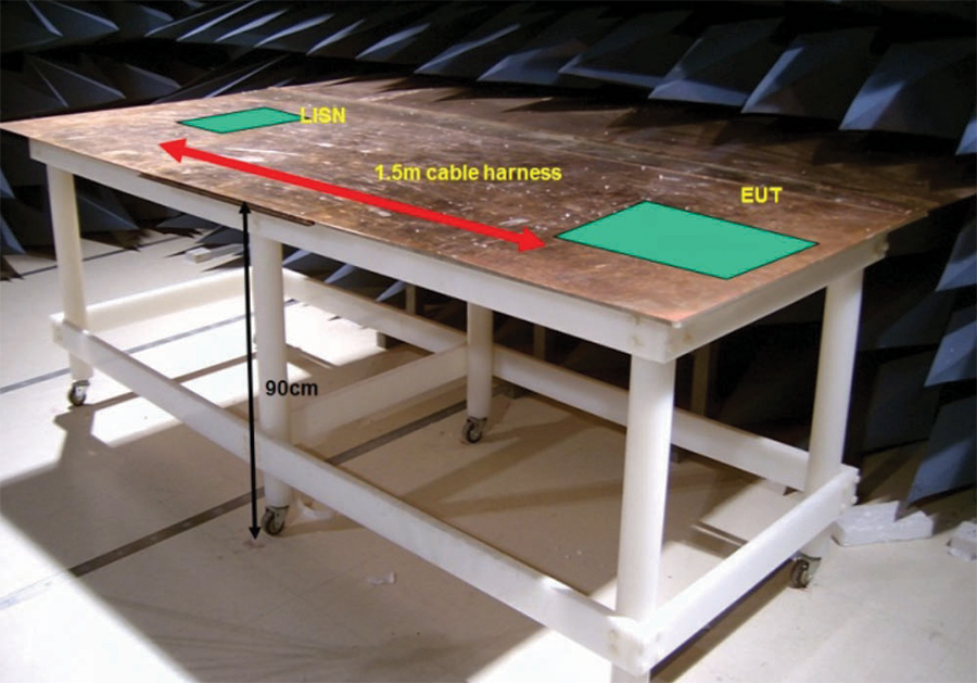
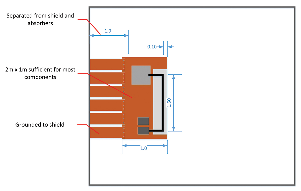
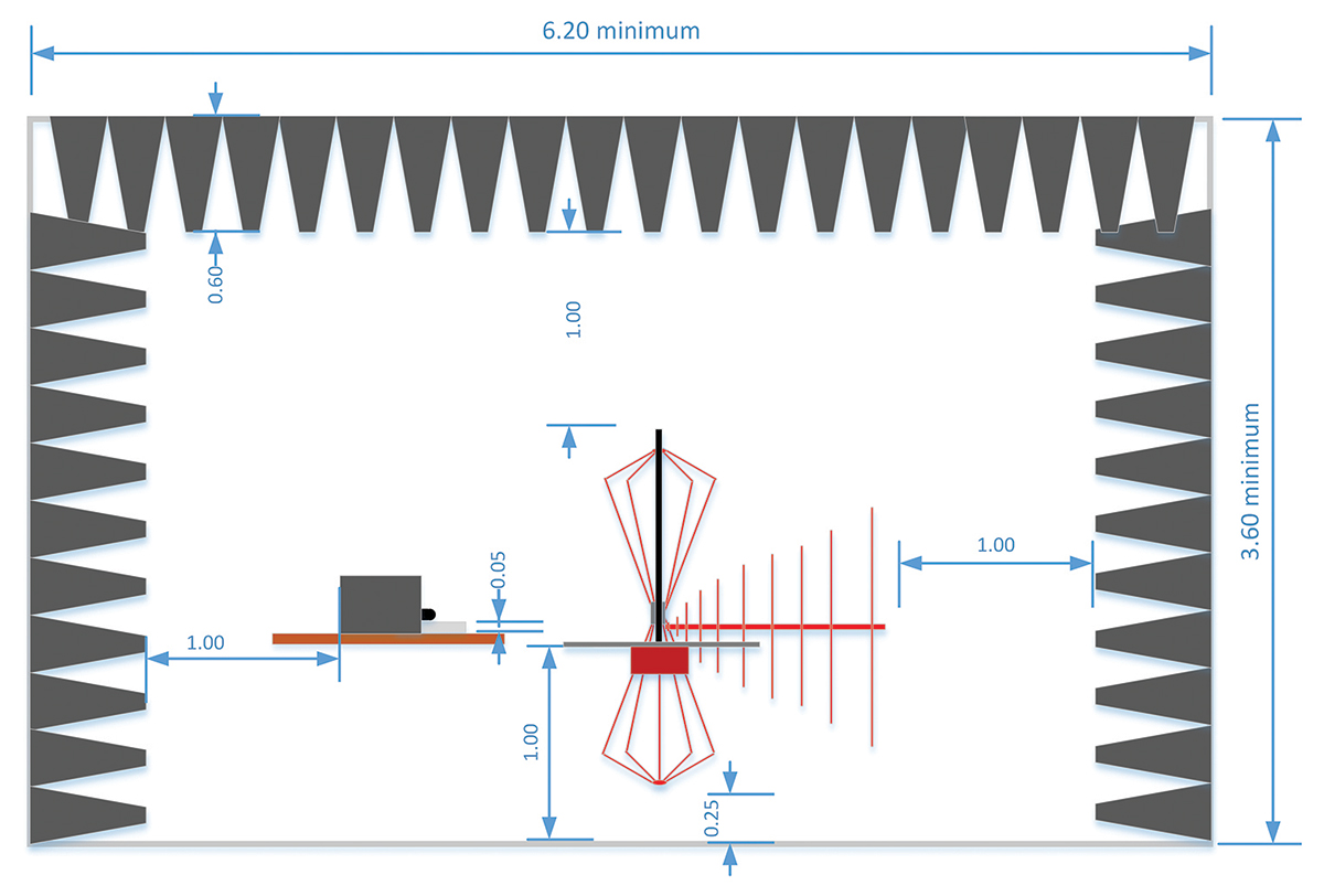
Figure 6 shows how the size of the bench is determined. The ground plane bench must extend all the way to the shield and in most cases, it is grounded to the wall of the shielded room. Grounding of the ground plane to the wall of the ALSE, especially if the chamber utilizes hybrid (ferrite/foam) absorbing material, has shown to reduce measurement system resonant conditions that may occur in the 10-70 MHz frequency range. The standard, however, does permit the bench to be grounded to the floor as an alternative.
As defined in CISPR 25, the minimum width of the reference ground plane (bench) for radiated emissions shall be 1000 mm, the minimum length of the ground plane for radiated emissions shall be 2000 mm, or the length needed to support the entire EUT plus 200 mm, whichever is larger.
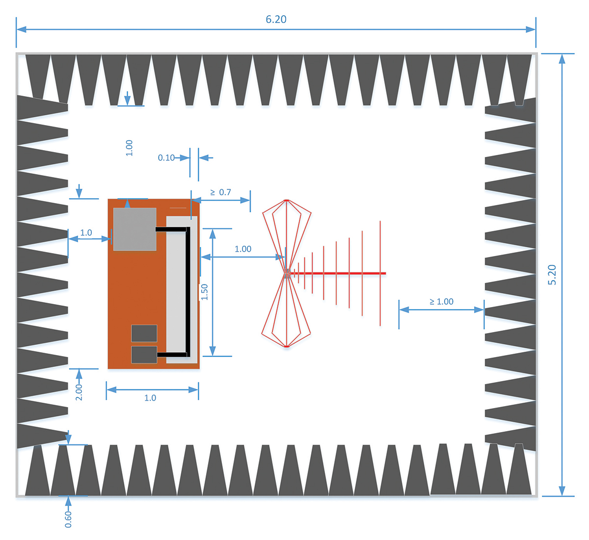
For the height and the length of the chamber, CISPR 25 further defines the separation distances to be followed in determining the minimum space needed. The first and most critical is the test distance where emissions are to be measured at a minimum distance of 1 m from the cable harness to the antenna.
The other rule states that no part of the antenna can be closer than 1 m away from the tips of the absorbing material. These rules and recommended antennas define the length and height of the chamber. The 1 m distance to the cable harness is measured from the axis of the antenna elements for the monopole rod and the biconical antenna. For the log periodic dipole array (LPDA), the distance is measured from the tip of the antenna. Finally, for the horn antennas the distance is measured from the front face or aperture plane of the antenna. The longest antenna is usually the LPDA. A typical LPDA for the 200 MHz to 1 GHz range is about 1 m in overall length. In addition to the 1 m test distance and the 1 m for the antenna length, we have a 1 m clearance from the back of the antenna to the tips of the absorber. Figure 8 also shows the reference distances for an LPDA and bicon antennas in the chamber for the CISPR 25 setup.
The height of the chamber will be driven by the longest antenna. The longest vertical antenna is usually the active rod monopole. The monopole is used with an extremely electrically small ground plane. Per the standard, the monopole rod is about 80 cm in length and it is positioned such that the ground plane is at the same level as the bench which as Figure 5 suggests is nominally 90 cm in height. The 1 m rule for the separation between the antenna and the absorber tip will again determine the minimum height of the chamber as shown in Figure 9.
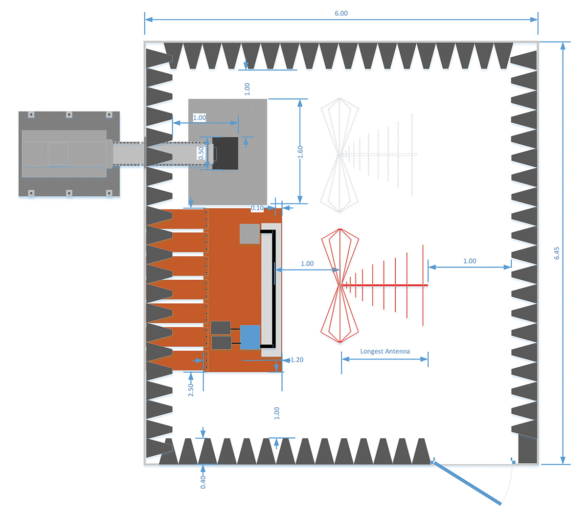
The CISPR 25 document prepared by the CISPR organization, and the requirements and guidelines on antennas and receivers, are already comprehensively defined in the CISPR 16-1-4 document [5]. The recommended antenna types used for the CISPR 25 measurements are therefore cross-referenced to the CISPR 16 document. For low frequencies, an active rod monopole antenna is preferred. At frequencies between 30 MHz and 200 MHz, a typical biconical antenna is the recommended antenna. From 200 MHz to 1 GHz, the antenna of choice is an LPDA and finally, from 1 to 5.95 GHz, the dual ridge horn (DRH) antenna can be a more compact and efficient antenna that easily meets the cross pole requirements of the standard, although lower gain LPDAs can still be used. It should be noted that bi-log antennas are not allowed for CISPR 25 measurements and all references to the bi-log antenna have been removed from CISPR 25 5th Edition.
CISPR 25 5th Edition contains an annex (Annex I) that provides methods to validate the performance of an ALSE used for component-level radiated emission tests. The ALSE validation annex (Annex J) in CISPR 25 4th Edition contained two methods (one method based upon reference measurements and another method based upon modeling) for validating the ALSE. However, after the 4th Edition validation methods were used for several years, the experts responsible for CISPR 25 decided to include only the chamber validation method based upon modeling for CISPR 25 5th Edition. The ALSE validation method in CISPR 25 currently covers the frequency range of 150 kHz to 1 GHz. However, this remains an informative annex and experts are discussing ALSE validation methods >1GHz for future editions of CISPR 25.
As mentioned at the beginning of the article, CISPR 25 also covers the measurement of emissions received by a vehicle antenna for a full vehicle setup. CISPR 25 5th Edition contains special setups to be used for the testing of electric vehicles (EVs) and hybrid electric vehicles (HEVs) and the modules (inverters, batteries, etc.) to be used on EVs and HEVs. The committee found that special testing and limits are required for the testing of these electric-driven vehicles and their components.
These vehicles represent a special case since there are high currents and voltages involved not only in normal operation but also during charging cycles. There will be more detailed information on the measurement setups to be used for EV and HEV measurements under different connection and charging scenarios. The testing adds new conditions for when the vehicle is not being driven, but connected to the mains or a charging station. This is currently already required as part of the European directive ECE Regulation 10, which outlines the EMC requirements for wheeled vehicles marketed in the European Union. Although ECE Reg 10 has its own limits for vehicle and ESA testing, it references both CISPR 25 and CISPR 12 for test setups and measurement techniques.
These tests are conducted at frequencies above 200 MHz and as discussed previously, the chance of resonant modes being developed inside the shield room is increased, so to reduce measurement errors the use of an absorber is required. The chamber is treated such that the reflectivity in the area of the EUT is -10 dB. Figures 3 and 4 show that for the 200 MHz to 18 GHz range, the -10 dB level is higher than the typical reflectivity of the recommended materials. This means that the same absorber used in the CISPR 25 chamber can be used in the ISO 11452-2 chamber, with the relevant guidance on minimal separation distances between DUT, absorbers, and antennas. Antenna selection is in keeping with the need to generate the required field levels in the most effective and efficient manner given the cost of amplifiers. It is recommended that a dual ridge horn antenna be used for the 200 MHz to 2 GHz range. Above that, octave horns and standard gain horns with high gain are the preferred antenna choice.
- CISPR 12 Vehicles, boats, and internal combustion engines – Radio disturbance characteristics – Limits and methods of measurement for the protection of off-board receivers 6nd ed. IEC Geneva, Switzerland 2007.
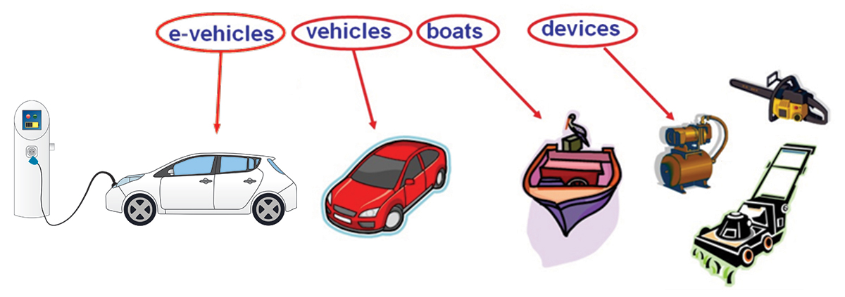
- CISPR 25 Radio disturbance characteristics for the protection of receivers used on board vehicles, boats, and on devices- Limits and methods of measurement 5th Ed. 2021.
- MIL-STD-461 Requirements for the control of Electromagnetic Interference Characteristics of Subsystems and Equipment Department of Defense Interface Standard 10 December 2007
- ISO-11452 Road vehicles — Component test methods for electrical disturbances from narrowband radiated electromagnetic energy — Part 2: Absorber-lined shielded enclosure Second Edition 2011-11-01
- CISPR 16-1-4 Specification for radio disturbance and immunity measurement apparatus and methods Part 1-4 radio disturbance and immunity measuring apparatus – Antennas and test sites for radiated disturbance measurements. 3rd Ed. IEC Geneva, Switzerland 2010.
- CISPR 36 Electric and Hybrid Electric Road Vehicles – Radio disturbance characteristics – Limits and methods of measurement for the protection of off-board receivers below 30MHz 1st ed. IEC Geneva, Switzerland 2020.

Photo © Jerry Ramie