lectromagnetic interference (EMI) issues that engineers encounter in the field are often due to poor layout design, with grounding layout problems being one of the primary contributors. From a radio frequency (RF) perspective, even a path with seemingly low resistance can present significant impedance. When RF currents are forced through this high-impedance path, a substantial RF voltage difference can develop. This voltage difference across what should be a common low-impedance ground can elevate noise levels.
This issue arises at both the printed circuit board (PCB) level and the system level. In this month’s column, we examine system-level troubleshooting techniques commonly used to identify grounding issues. We also demonstrate how improvements to system grounding can effectively reduce noise.
In this case study, the equipment under test (EUT) is a bi-directional power converter that uses two IGBT-based drive systems to deliver large bursts of power for mission-critical applications. As shown in Figure 1, we set up an on-site conducted emission test using a 32A three-phase LISN. Figure 1 also displays the initial conducted emission scanning results, showing several frequency bands where the EUT failed to meet compliance.

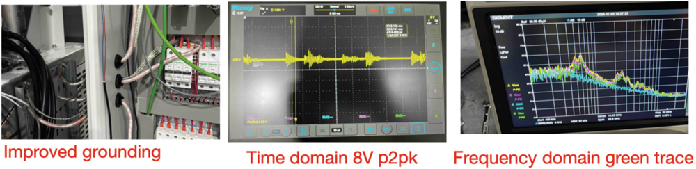
While we waited for the new filters to arrive, there was still another noise issue to address at around 2 MHz, caused by a different resonance source. This noise could not be mitigated even with a three-phase four-wire filter, requiring an entirely different approach to address it. Upon reviewing the system design, we found that both motor drives were located in one inner compartment, connected via wires to the magnetics compartment, which contains the low‑frequency choke, capacitors, transformers, and EMI filters. We questioned whether the ground difference (or ground bounce) between the drive and magnetics compartments could be contributing to the noise at 2 MHz.
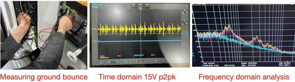
To investigate this, we measured the ground potential difference. Although several tools are available for measuring noise in this frequency range (after all, it is only 2 MHz),1 we opted for the Onfilter Power Line EMI Adapter.2,3 This adapter provides complete galvanic isolation from high mains voltages while allowing a direct path for high-frequency signals. This setup enabled us to connect our sensitive instruments to live power lines safely and measure EMI between different grounded parts without creating ground loops.
In Figure 2, we conducted the measurement by tapping the probe tips between the two grounding points in question. Measurements in both the time and frequency domains confirmed that this ground difference contributed to the noise observed at 2 MHz.
- Min Zhang, Signal Integrity Journal, “Troubleshooting Low Frequency Common Mode Emissions,” February 1, 2023.
- Ken Wyatt, the EMC blog, EDN, “Review: Tool Measures Power-line EMI,” November 25, 2020.
- Power Line EMI Adapter MSN15 https://www.onfilter.com/emi-adapter-msn15
