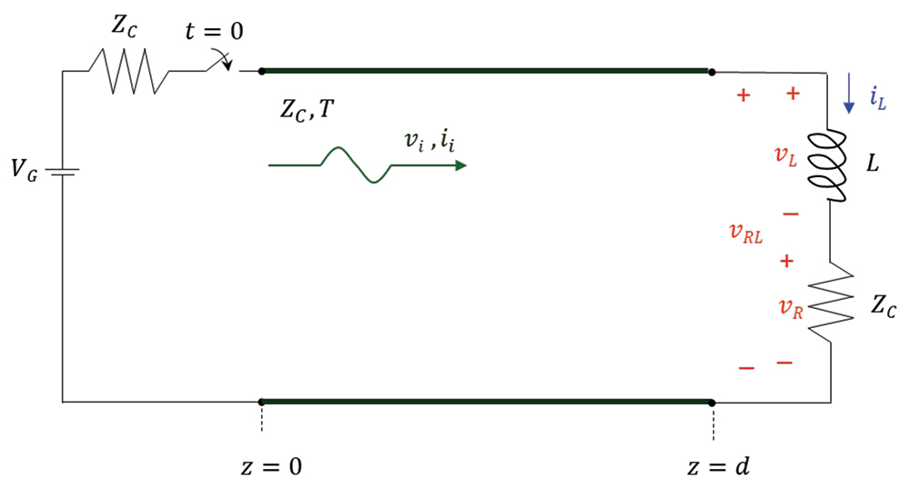
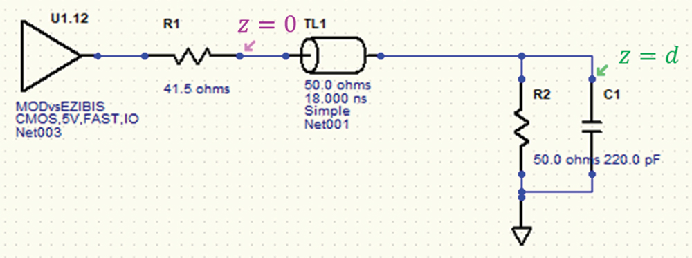
his article discusses the reflections on a transmission line terminated with either an RL or an RC load. The detailed analytical derivations are verified through the HyperLynx simulations and laboratory measurements.
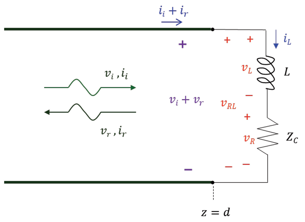
Note that the load resistor value is equal to the characteristic impedance of the transmission line; it is also assumed that the initial current through the inductor is zero, iL(0_) = 0.


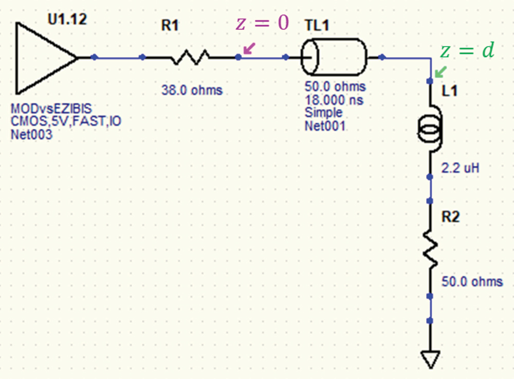
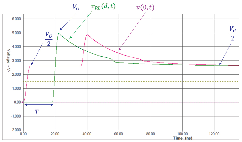
The simulation results are shown in Figure 1.4.
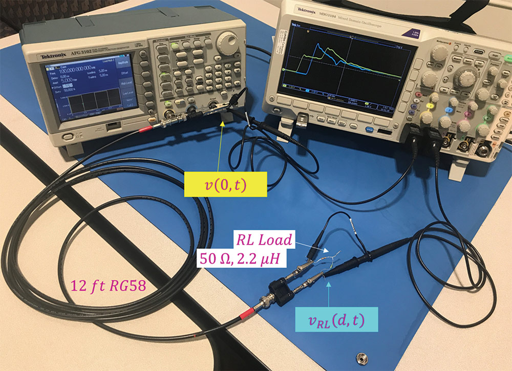
The measurement results are shown in Figure 1.6.
Note that the measurement results verify the simulation and the analytical results.
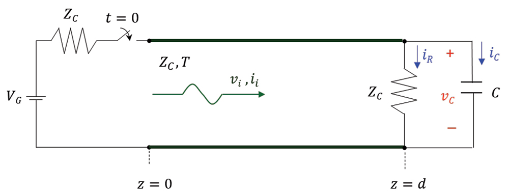
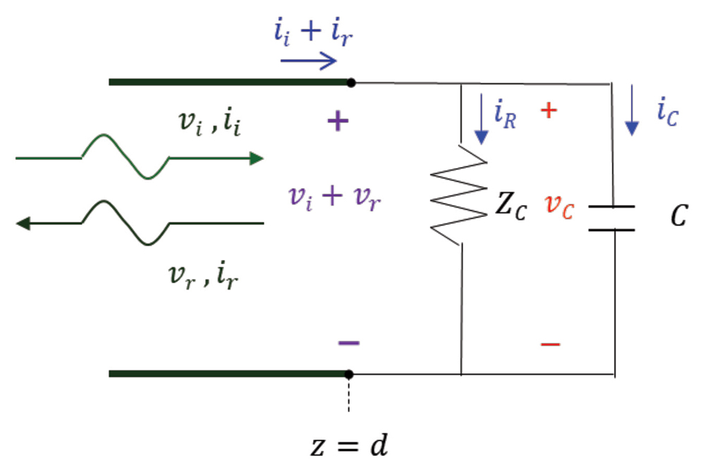
Note that the load resistor value is equal to the characteristic impedance of the transmission line; it is also assumed that the initial voltage across the capacitor is zero, vC(0_) = 0.
The reflected current wave is related to the reflected voltage wave by Eq. (1.1c). KVL and KCL at the load produce


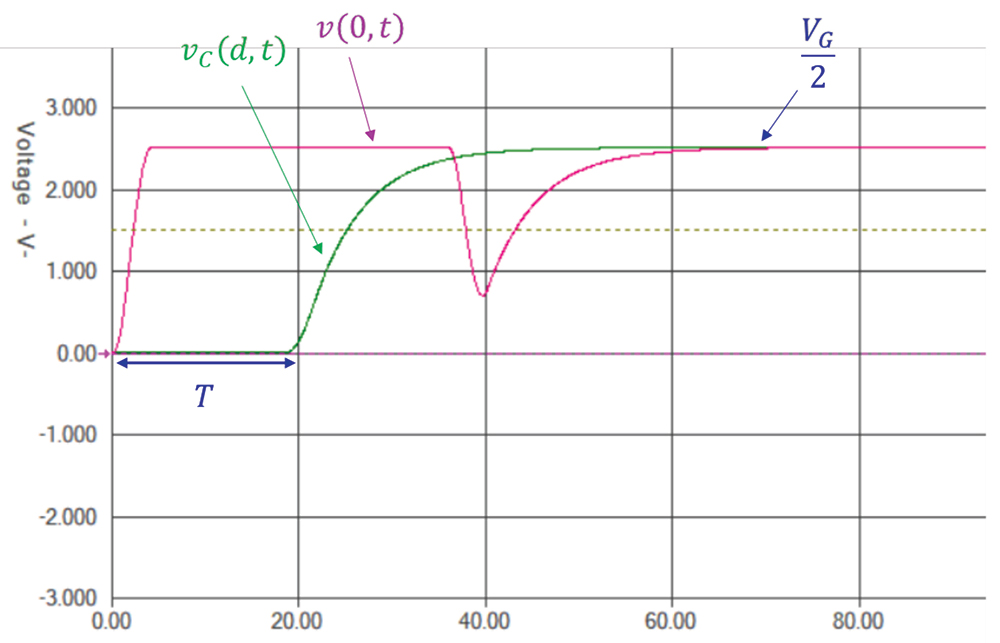
The simulation results are shown in Figure 2.4.
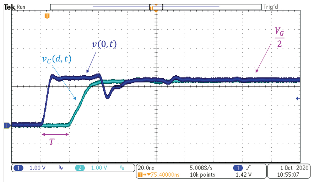
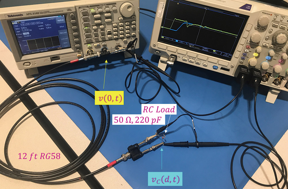
The measurement results are shown in Figure 2.6.
Note that the measurement results verify the simulation and the analytical results.
- Adamczyk, B., “Transmission Line Reflections at a Reactive Load,” In Compliance Magazine, December 2018.
- Adamczyk, B., “Transmission Line Reflections at a Resistive Load,” In Compliance Magazine, January 2017.
- Adamczyk, B. Foundations of Electromagnetic Compatibility with Practical Applications, Wiley, 2017.

