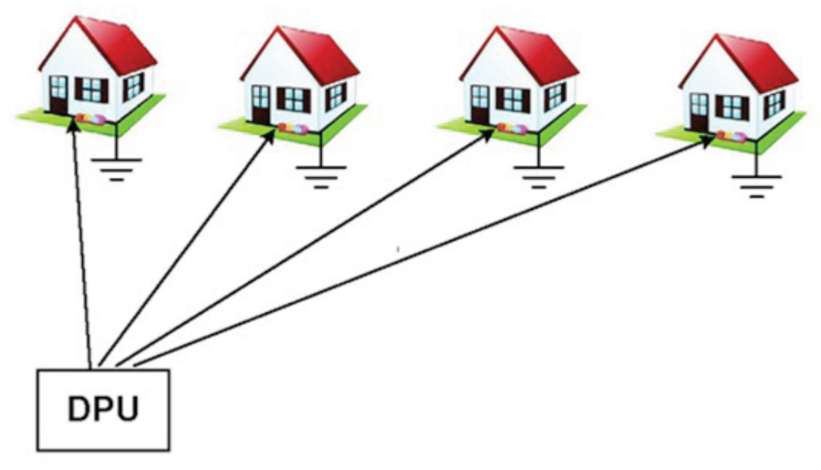
uch has been written about failures due to ground potential rise (GPR). So, is there anything more to say? Well yes. What has been written has generally been about single houses with multiple grounds. But often there is not just a single house, but multiple houses all potentially interconnected via a single piece of equipment. For example, in homes connected to a distribution point unit (DPU) (see Figure 1) the DPU is often a fiber-to-the distribution point (FTTdp) unit, or a digital subscriber line access multiplexer (DSLAM). So, what happens in this case?
Well, what could happen is insulation failure. This kind of failure was discussed in a 2011 study by the Japanese telecommunications company Nippon Telegraph and Telephone (NTT). That company had a problem. About 0.05% of their optical network terminal/home gateway ONT/HGW boxes stopped working due to insulation failure. Now 0.05% doesn’t sound like much, but with 15 million installed devices, that amounted to 7500 units per year. Their research showed that the 0.05% failure rate corresponded to a 7.7 kV surge. Assuming that 0.05% (or less) is an acceptable failure rate, could GPR cause the corresponding 7.7 kV insulation failure?

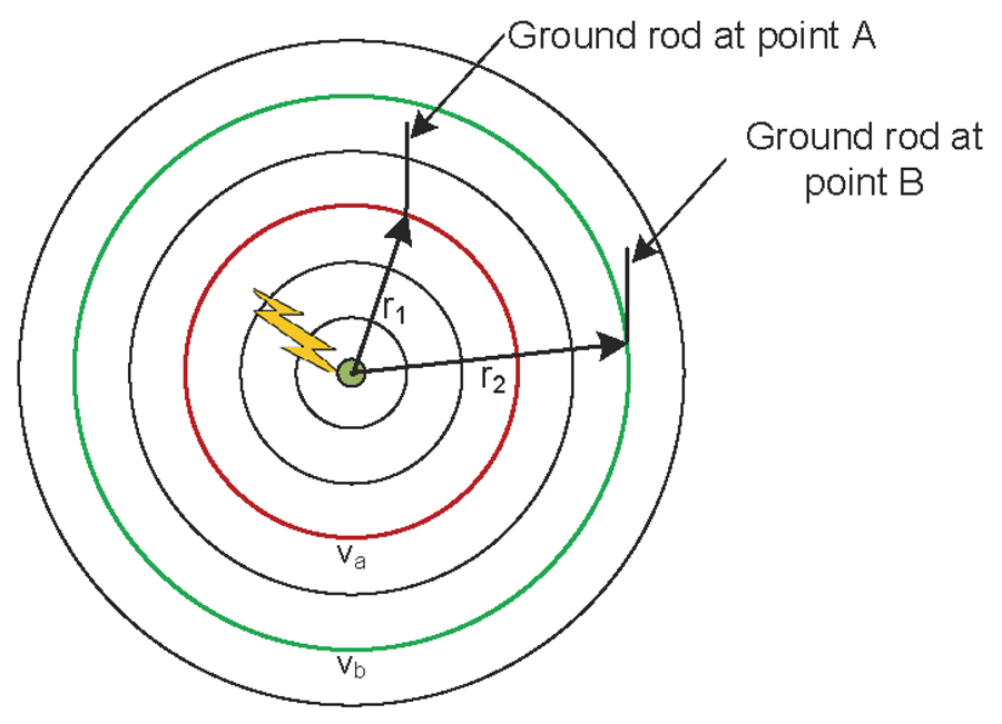
Now suppose there are grounding points A and B located on different lightning-induced equipotential surfaces like those shown in Figure 3.
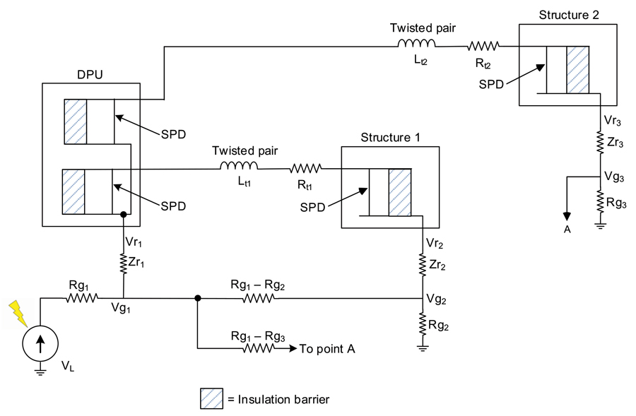
So, let’s see how this analysis can be extended to multiple houses, all potentially interconnected via a single piece of equipment.
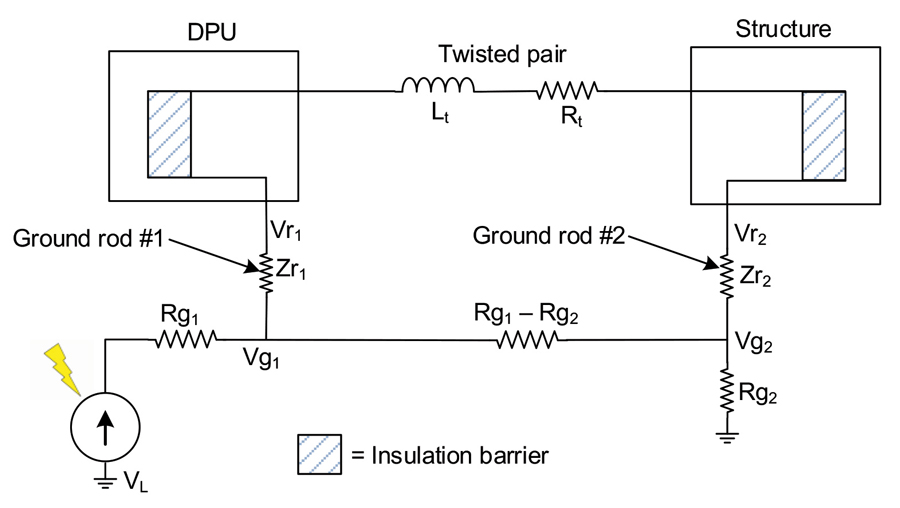
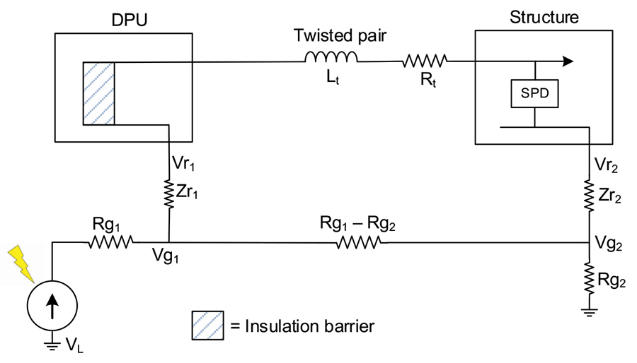
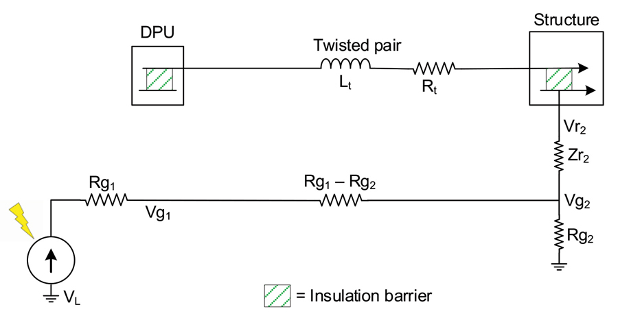
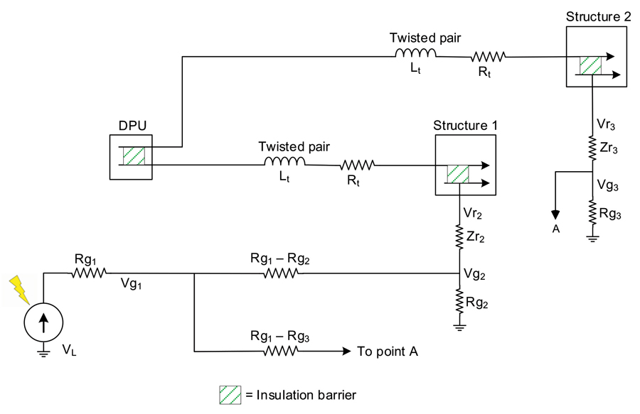
Case 1 in which both the DPU and the houses are grounded and connected by an unshielded twisted-pair POTS line (see Figure 4). This case applies to both FTTdp and DSLAM. There are three subcases:
- Case 1a where there are no protectors installed on the POTS line
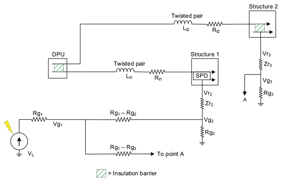
- Case 1b where one protector is installed on the POTS line
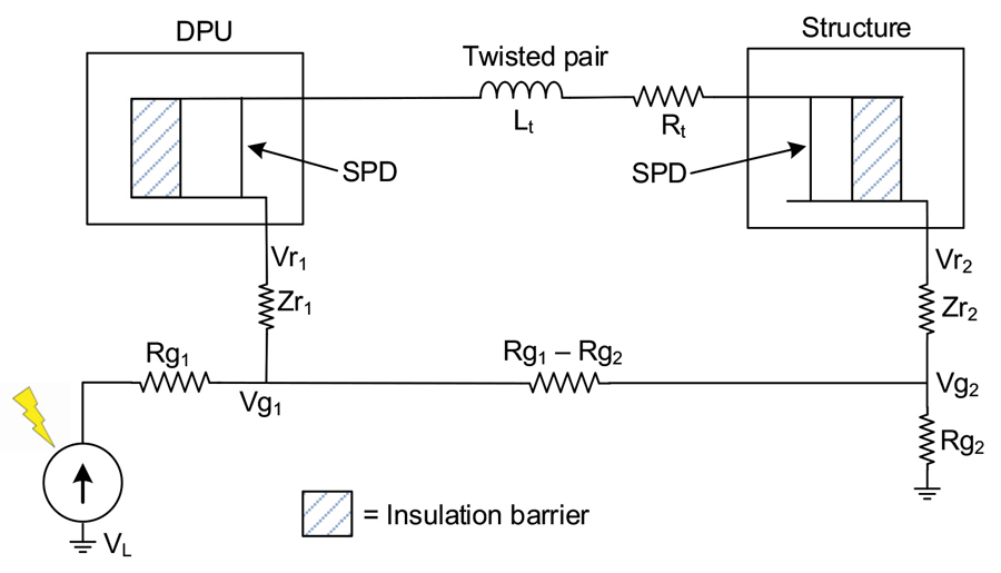
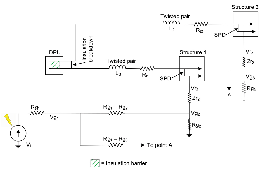
- Case 1c where there are protectors at both ends of the POTS line
- Case 1a where there are no protectors installed on the POTS line
- Case 1b where one protector is installed on the POTS line
- Case 1c where there are protectors at both ends of the POTS line
- Case 2a where there are no protectors installed on the POTS lines
- Case 2b where one protector is installed on one of the two POTS lines
- Case 2c where protectors are installed on the POTS lines at the houses
- Case 2a where there are no protectors installed on the POTS lines
- Case 2b where one protector is installed on one of the two POTS lines
- Case 2c where protectors are installed on the POTS lines at the houses
In this figure:
- Rg1 is the ground resistance between the lightning strike point and the nearest ground rod (#1)
- Rg2 is the ground resistance between the farthest ground rod (#2) and infinity
- Zr1 is the impedance of ground rod #1
- Zr2 is the impedance of ground rod #2
- Rt is the resistance of the twisted pair
- Lt is the inductance of the twisted pair
- Vr1 is the voltage across ground rod #1
- Vr2 is the voltage across ground rod #2
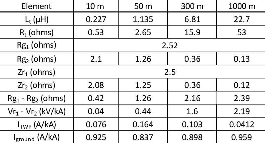
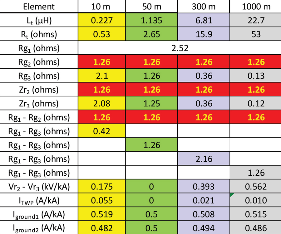
- The lightning flash is a 30 kA 4.5/75 median lightning surge from CIGRE TB549.
- The lightning flash is 50 m from the DPU.
- The maximum distance of the FTTdp from a house is 300 m
- The maximum distance of the DSL from a house is 1000 m
- The minimum distance of both FTTdp and DSL from a house is 10 m
- A 22 AWG twisted pair is the connection between the DPU and the house
- An 8-foot 5/8-inch diameter ground rod
A uniform ground of resistivity ρ of 400 ohm-m (about average, according to MIL-HDBK-419).
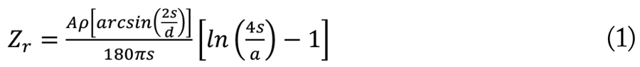
From Grcev [3]:


β = 0.170
A = 0.240
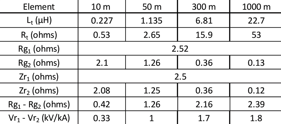
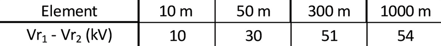
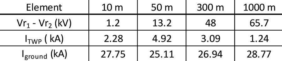
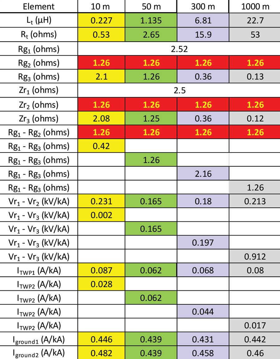
For a median strike, TB549 Table 3.5 shows a lightning current of 30 kA, which in this case would produce the peak voltage difference shown in Table 4.
Comparing Table 6 to Table 5, the voltages and currents drop as more houses are added. The amount by which they drop depends on the relative values for the elements in the case considered.
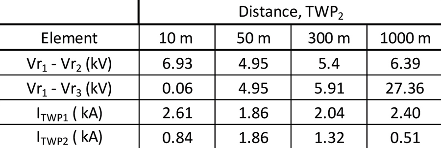
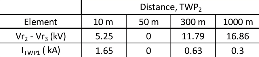
Looking at the tables for a 30 kA 4.5/77 lightning strike, the peak GPR could be anywhere from 1.2 kV to 66 kV, depending on the assumptions made. For Case 1c where there is a connection between the DPU and the houses, there is a current flow that could potentially be destructive.
To visualize the results, the GPR voltages in Table 2 and Table 4 are plotted in Figure 12. The initial portion of the plot for Case 1c shows the effect of the ground rod.
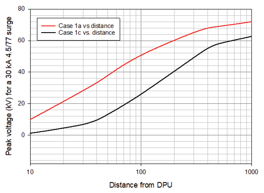
This case looks less severe than Case 1, but the peak GPRs could be enough to cause problems.
- Martin, A. R., 2011a, “A new TIA standard for equipment installations with two or more separate grounds,” Alliance for Telecommunications Industry Solutions (ATIS) PEG Conference 2011, https://www.atis.org.
- Martin, A.R., “How Grounds Affect the Peak Voltage Due to Lightning,” In Compliance Magazine, April 2021, pp 37-40
- Grcev, L., “Impulse Efficiency of Ground Rods,” IEEE Transactions on Power Delivery, vol. 24, no. 1, January 2009, pp 441-451.
- Pretorius, P. H., “Was Lightning Ground Potential Rise Overlooked in the Design of Large Earth Electrodes?” EE Publishers, March 26, 2018.
- Tominaga, Tetsuya, “Damage to Equipment in Japan” ITU-T Study Group 05, Technical Session on Home Networks Geneva, 29/04/2011, https://www.itu.int/dms_pub/itu-t/oth/06/52/T06520000020001PPTE.ppt.
- Ardley, Tim, “Protecting PoE PSE and Ethernet to the latest international OSP standards,” The Alliance for Telecommunications Industries Solutions Protection Engineers Group, Monroe, LA, April 2016.
- Wiese, Jim, “Evolving Ethernet Applications Have Resulted in Protection Challenges,” The Alliance for Telecommunications Industries Solutions Protection Engineers Group, Littleton, CO, March 2014.
- Okugawa, Yuichiro, Honma, Yasuhiro, and Takaya, Kazuhiro, “EMC Technology that Protects Network Equipment from Electromagnetic Problems,” NTT Technical Review, March 2014, vol. 12, no. 3.
