Feature Article
Performing Proximity Magnetic Fields Immunity Testing
How to Conduct Testing in Accordance with IEC 60601-1-2:2014 Amendment 1:2020

EC 60601-1-2 is the international standard on electromagnetic disturbances to medical electrical equipment and is used in support of worldwide regulatory approvals for medical electrical equipment. The latest edition of the IEC 60601-1-2 standard, IEC 60601-1-2:2014 Amendment 1:2020 (referenced as Edition 4.1 hereafter), was published September 1, 2020. This latest edition includes the following significant technical changes with respect to its previous edition (IEC 60601-1-2 Edition 4.0 2014-02, referenced as Edition 4.0 hereafter):
- Normative references—As listed in Table 1, standard versions of eleven normative references are updated. In addition, ISO 7137:1995 is deleted and IEC 61000-4-39:2017 is added.
-
Power input voltages—Power input voltage requirements for the following tests have been clarified: conducted disturbances (CISPR 11), voltage dips immunity (IEC 61000-4-11), and voltage short interruptions and voltage variations immunity (IEC 61000-4-11).
For conducted disturbances and voltage dips immunity measurements, testing shall be performed at both minimum and maximum rated voltages. If the difference between the minimum and the maximum rated input voltages is less than 25% of the highest rated input voltage, the tests may be performed at any one rated voltage. Please note each economy/region may have its own requirements. For example, South Korea requires that testing be performed at 220 V.
Testing of voltage short interruptions and voltage variations immunity shall be performed at any one voltage. Again, each economy/region may have its own requirements.
- Conducted immunity to SIP/SOPS (IEC 61000-4-6)—This test is now applicable to SIP/SOPS on cables equal to or greater than 1 m in length (versus 3 m from Edition 4.0).
- Immunity to proximity magnetic fields—This is a newly added requirement stipulated in Subclause 8.11 of Edition 4.1 with the title of “Immunity to proximity magnetic fields in the frequency range 9 kHz to 13.56 MHz.” It applies to medical electrical equipment or systems that contain magnetically sensitive components or circuitry with a less than 0.15 m separation distance from the field sources of 30 kHz, 134.2 kHz, and 13.56 MHz.
- Annex F—Annex F, an informative annex, has been replaced by a new one. The title of the annex has been changed from “RISK MANAGEMENT for BASIC SAFETY and ESSENTIAL PERFORMANCE with regard to ELECTROMAGNETIC DISTURBANCES,” to “Guidance on the application of RISK MANAGEMENT with regard to ELECTROMAGNETIC DISTURBANCES in this collateral standard.”
The following sections describe the proximity magnetic fields immunity test, and the key technical changes.
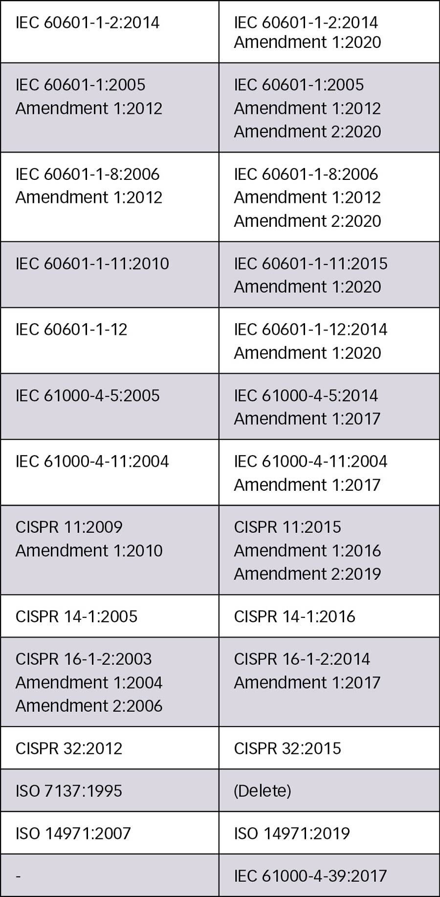
Table 1: Normative references
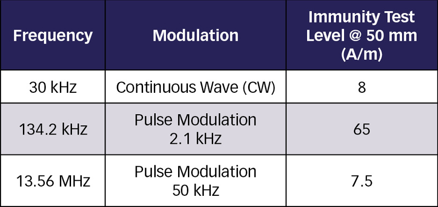
Proximity magnetic fields immunity test requires three frequencies to be tested: 30 kHz, 134.2 kHz, and 13.56 MHz. Test frequencies, test signal modulation, and test levels are listed in Table 2.
Test levels listed in Table 2 are the amplitude of unmodulated carrier signal (i.e., continuous wave, CW). For testing at the frequencies of 134.2 kHz and 13.56 MHz, the carrier signals are pulse-modulated using a 50% duty cycle square wave signal and with specified modulation frequencies.
Test equipment includes a generator, an optional compensation network, a radiating loop antenna, a monitoring loop antenna, and an electromagnetic interference (EMI) receiver or spectrum analyzer.
The generator must have the capability of generating the desired test levels. It includes a signal generator and a power amplifier. A signal generator must be capable of generating a carrier signal for the frequencies of interest and be equipped with pulse modulation capability internally or externally.
Based on experience using radiating loop antennas from two manufacturers, an 80 watts power amplifier should be able to generate the desired test levels. Manufacturers of radiating loop antennas typically provide drive power information for its radiating loop antennas. It is important to ensure the power amplifier is not saturated and the EMI receiver or spectrum analyzer is not overloaded.
A test laboratory with IEC 61000-4-6 10 Vemf test capability may use the same signal generator and power amplifier from its IEC 61000-4-6 test equipment if the signal generator and power amplifier cover frequencies of 30 kHz and 134.2 kHz. Though IEC 61000-4-6 specifies the test frequency range from 150 kHz to 80 MHz (not covering 30 kHz and 134.2 kHz), a power amplifier may work for frequencies below 150 kHz even if its specification starts at 150 kHz.
A matching network (compensation network) is used to better match the voltage standing wave ratio (VSWR) in the system to reduce needed power and to prevent damage to the power amplifier from reverse power. If a matching network is used, it connects directly to a radiating loop or through a specially designed cable. At the time of this writing, a 13.36 MHz matching network is commercially available, but a matching network can be made in-house with all the required components typically costing less than $100. A vector network analyzer (VNA) is used to tune the matching network.
A radiating loop antenna is a field-generating device. A monitoring loop antenna is a magnetic field sensor loop. Specifications for these loop antennas are listed in Table 3.
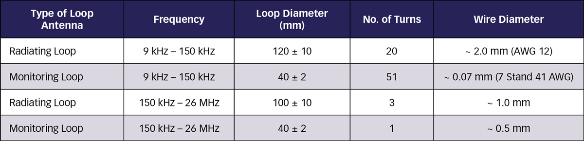
Table 3: Loop antenna specifications
Both radiating and monitoring loop antennas are commercially available. Equipment manufacturers offer loop antennas as individual parts or as kits. Kits typically come with 50 mm fixtures.
Radiating loop antennas can also be made in-house. Step-by-step instructions are provided below to construct a 134.2 kHz radiating loop antenna:
- Find a cylindrical form 120 ±10 mm in diameter, and 100 mm in height. The cardboard center of a wire spool of about 120 mm should work for the purpose.
- Wrap 20 turns of AWG 12 wire around the center of the form, leaving a few feet free on either end.
- Create a compensation network using a piece of prototyping board or other material with a coaxial connection for the amplifier on one side and terminals for the loop on the other. An optional step-down transformer may be used to increase the impedance as recorded by the amplifier and to produce the necessary drive current in the loop. The transformer must be rated for the test frequency and drive current.
- Connect the loop and the compensation network to a calibrated VNA and measure the impedance at the design frequency (e.g., 134.2 kHz).
- Add series capacitance to the compensation network to move the impedance to the Re(Y)=1 circle, Im(Y) < 0.
- Add parallel capacitance to the compensation network to move the impedance to the center (match).
Build up the capacitors on a breadboard first, then solder them on a prototyping board, and place the board in an enclosure with dual banana jacks. A TESEQ NSG 4070 conducted immunity system is used to power the loop antenna and obtain the required 65 A/m with less than 10 watts of power.
Figure 1 shows the test setup to establish test levels.
The monitoring loop antenna is positioned on the center axis of the radiating loop antenna and at a distance of 50 mm. Loop antenna manufacturers offer fixtures to keep the monitoring loop antenna at a distance of 50 mm from the radiating loop antenna.
The monitoring loop antenna is connected to an EMI receiver or a spectrum analyzer. The magnetic field strength (in dBµA/m) at the distance of 50 mm is calculated as the sum of the measured voltage level (in dBµV) and the conversion factor (in dB/Ωm) of the monitoring loop antenna. The conversion factor is used to convert the monitoring loop antenna voltage to magnetic intensity. The relevant conversion factor can be found in the datasheet of the monitoring loop antenna. The measured field strength must be within ± 10 %. of the specified test level.
To achieve the desired magnetic field strength (for example, 7.5 A/m (137.5 dBµA/m) at 13.35 MHz), increase the power of the generator at the input of the radiating loop antenna (or the input of the matching network if a matching network is used) until the measured voltage at the output of the monitoring loop antenna is reached. For a conversion factor of 18.3 dB/Ωm, the measured voltage is 119.2 dBµV. No modulation signal is applied while establishing test levels. Record the signal generator output levels for testing.
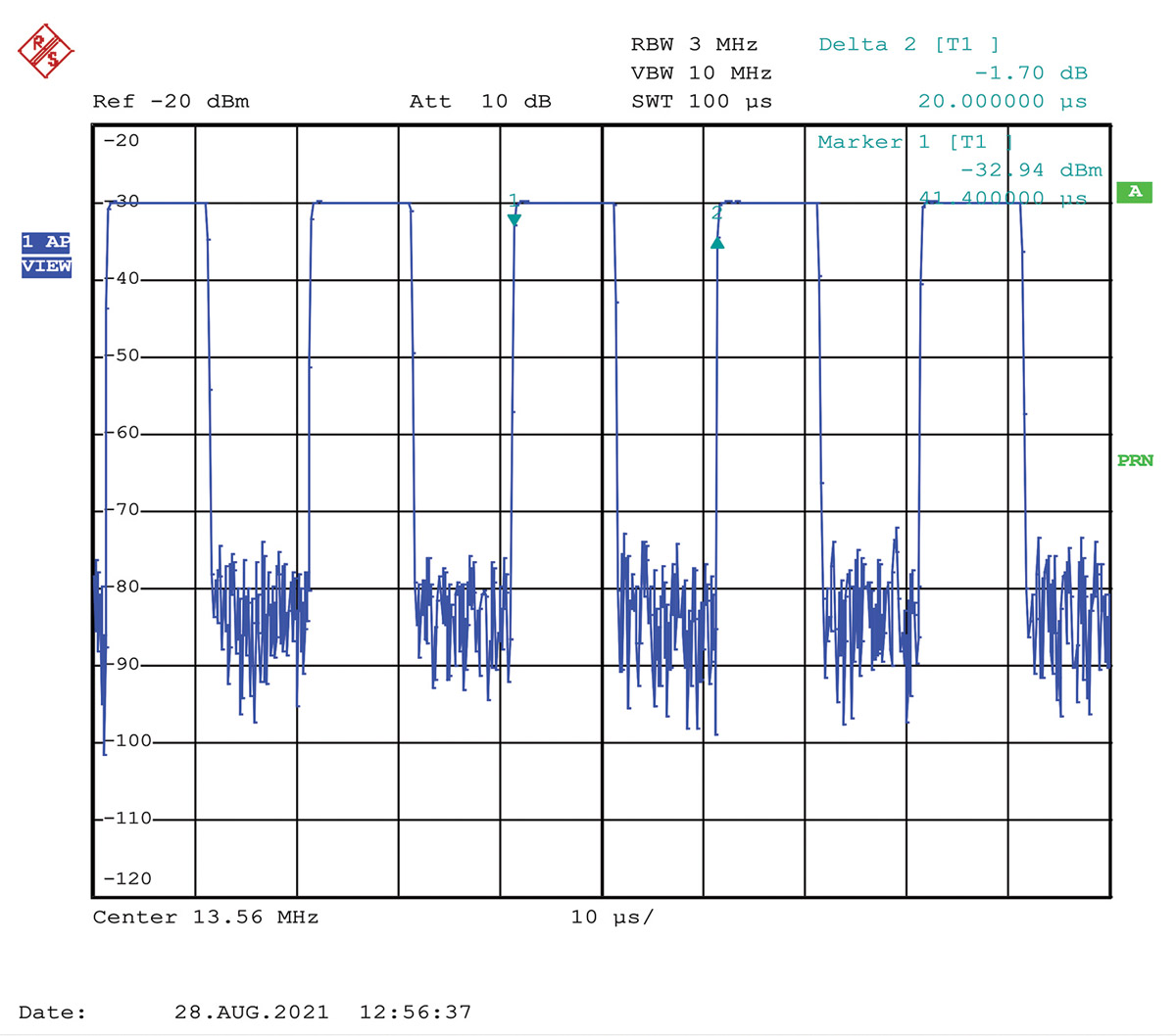
Once the measured voltage is reached, switch on the modulation of the test signal to verify the correct modulation of the test signal. To verify the modulation, set the span of an EMI receiver (in spectrum mode) or a spectrum analyzer to zero, as shown in Figure 2. A pulse frequency of 50 kHz is equivalent to a pulse period of 20 µs.
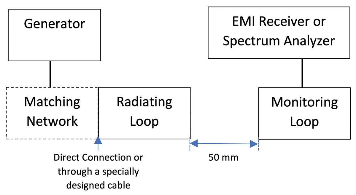
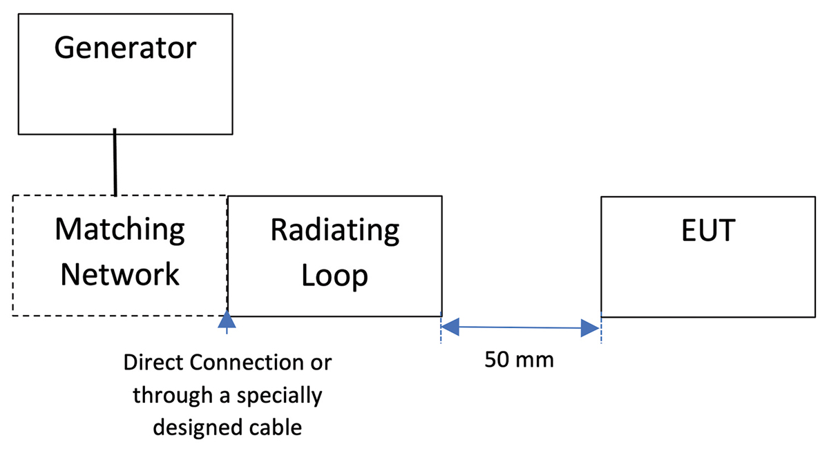
Figure 3 shows the test setup to execute the test.
Test methods are specified in IEC 61000-4-39:2017. The test is performed by exposing the equipment under test (EUT) to the test signals at 30 kHz, 134.2 kHz, and 13.56 MHz. Place the radiating loop antenna at the test distance of 50 mm from a test point on the EUT. Orient the plane of the radiating loop antenna parallel to the EUT’s faces. Set the signal generator’s output level to the level recorded from established test levels.
The dwell time must be long enough for the EUT to adequately respond to the test signal. The minimum dwell time is 2 seconds.
IEC 60601-1-2 Edition 4.1 2020-09 CONSOLIDATED VERSION supersedes IEC 60601-1-2 Edition 4.0 2014-02. Each economy/region sets its own transition period. In the U.S., the Food and Drug Administration (FDA) will no longer accept Edition 4.0 test reports after the end of the transition period of December 17, 2023.
Being prepared for the changes and requirements is important to your success. Table 4 lists a summary of tests required and specified in Edition 4.1, including the completely new proximity magnetic fields immunity test.
- IEC 60601-1-2:2014 Amendment 1:2020, Medical electrical equipment – Part 1-2: General requirements for basic safety and essential performance – Collateral Standard: Electromagnetic disturbances – Requirements and tests
- IEC61000-4-39:2017, Electromagnetic compatibility (EMC) – Part 4-39: Testing and measurement techniques – Radiated fields in close proximity – Immunity test
- IEC 61000-4-6:2013, Electromagnetic compatibility (EMC) – Part 4-6: Testing and measurement techniques – Immunity to conducted disturbances, induced by radio-frequency fields
- Schwartzbeck FESP 5132 Datasheet
http://schwarzbeck.de/Datenblatt/k5132.pdf - AMETEK CTS LAS 6100 Datasheet
https://www.ametek-cts.com - AMETEK CTS LAS 6120 Datasheet
https://www.ametek-cts.com
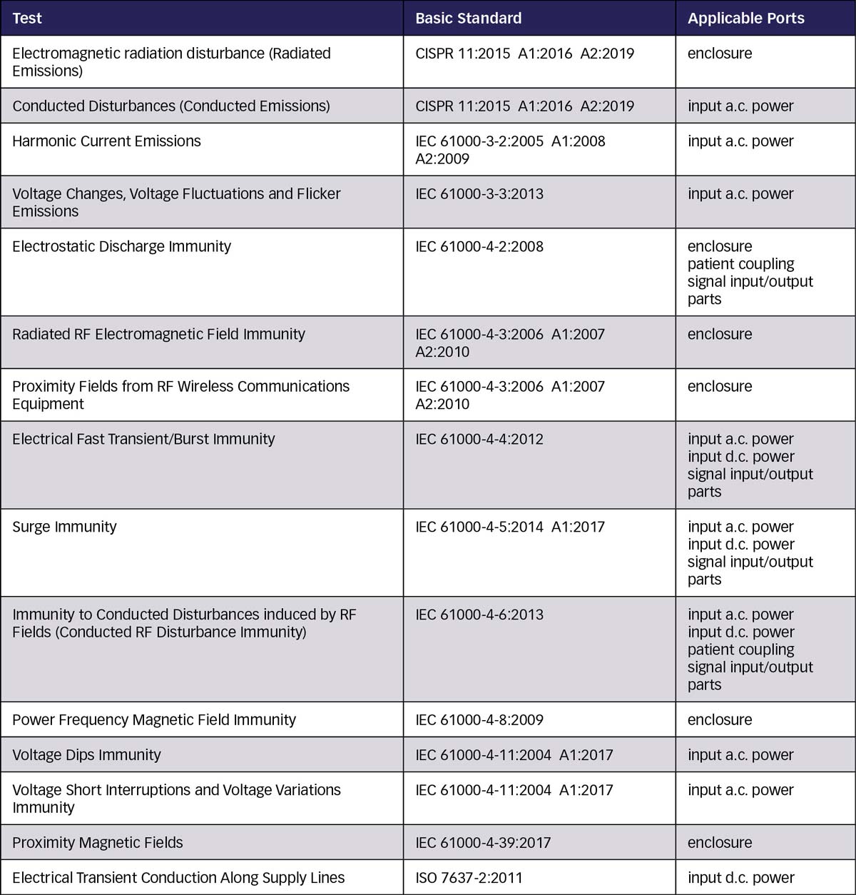
Table 4: Summary of tests specified in IEC 60601-1-2 Edition 4.1

Grace Lin is a Regulatory Compliance Engineer at HYTORC. Prior to joining HYTORC, she was an EMC staff engineer and a TCB reviewer at Intertek. Lin can be reached at glin@hytorc.com.

Brian Lackey is an EMC engineer and member of the technical staff at Intertek in Lexington, Kentucky. He is a member of the TCB Council, an organization responsible for directly interfacing with the FCC, and is developing standards with the IEEE for statistical process control. Lackey can be reached at brian.lackey@intertek.com.