Part I: Transmission Line Model, Equations and Their Solutions, and the Concept of the Input Impedance to the Line
n the previous article, [1], a concept of the phasor was introduced. This tutorial article is a part of the three-article series devoted to the frequency-domain analysis of a lossless transmission line. First, a time-domain model of a lossless transmission line is shown and used to arrive at the time-domain equations describing it. Next, the time-domain solution is transformed into the phasor domain. Subsequently, the general solution for the voltage and current is presented and followed by the concept of the input impedance to the line.
1. Transmission Line Equations
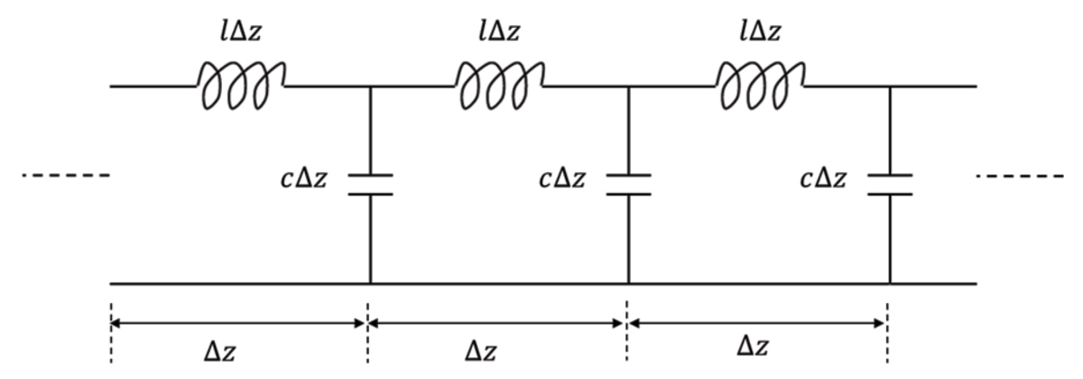
A lossless transmission line can be modeled as a distributed parameter circuit consisting of a series of small segments of length Δz as shown in Figure 1.
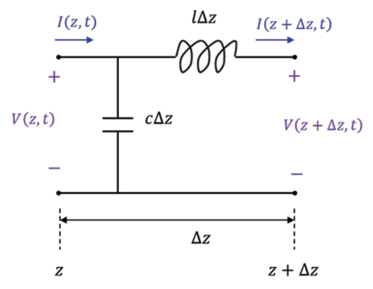
To obtain the transmission line equations, [2], let us consider a single segment of a lossless transmission line shown in Figure 2.
The distributed, per-unit-length parameters describing the transmission line are the inductance l in H/m and the capacitance c in F/m.
Writing Kirchhoff’s voltage law around the outside loop results in


2. General Solution of the Transmission Line Equations
The general solution of Eqns. (1.18) is of the form


where the characteristic impedance of the transmission line, Zc, is given by

and the constants and are obtained from the knowledge of a complete transmission line model (as we will show in the next article).
Before proceeding any further, let us verify that the Eqns. (2.1) are indeed the solutions of Eqns. (1.18). First, let us demonstrate this for Eq. (2.1a).


Differentiating Eq. (2.1b) with respect to z gives


3. The Complete Circuit Model of a Transmission Line
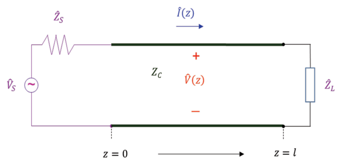
To determine the voltages and currents along the transmission line we need to consider a complete circuit model consisting of the source, the transmission line, and the load, as shown in Figure 3.
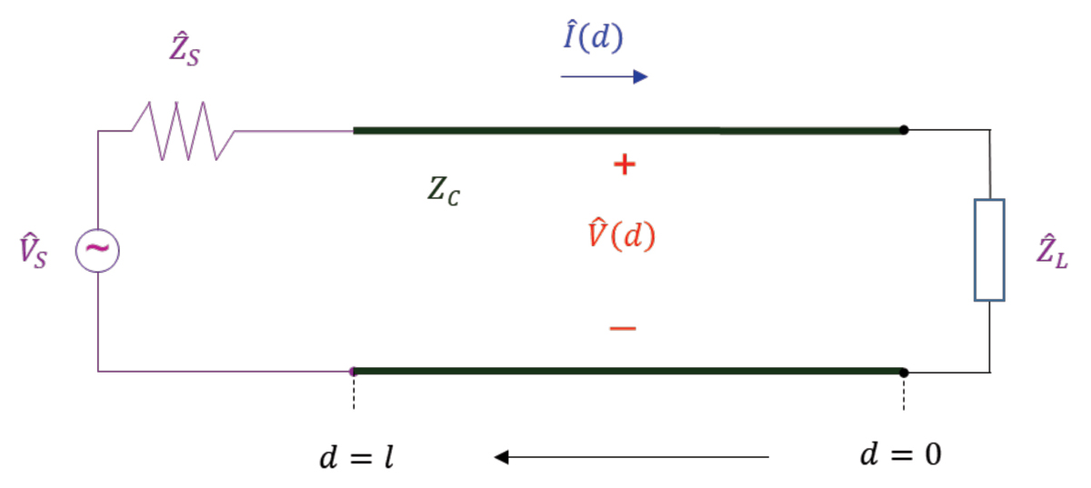
In this model, we are moving from the source located at z = 0, towards the load located at z = l. It is often convenient to use an alternate circuit, shown in Figure 4.
In this alternate model, we are moving from the load located at d = 0, towards the source located at d = l.
4. Concept of the Input Impedance to the Transmission Line
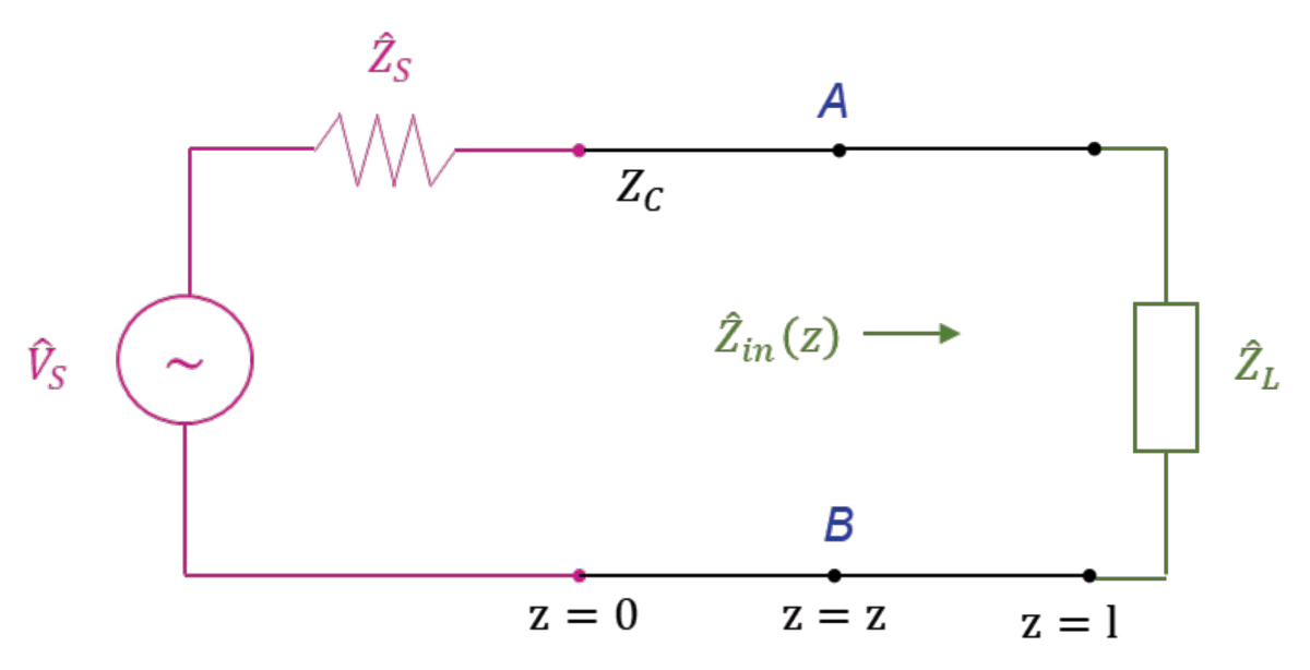
Consider a transmission line circuit shown in Figure 5.
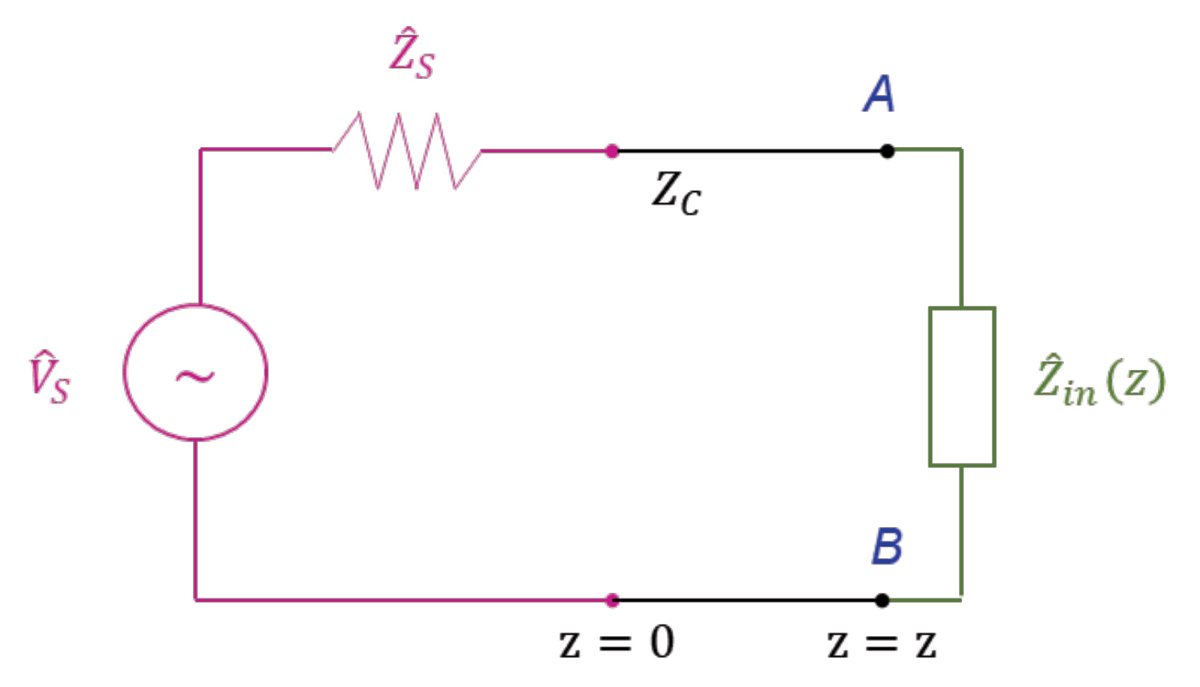
The input impedance to the line at any location z, Zin (z), is always calculated looking towards the load, regardless whether we use Model 1 or Model 2. Figure 6 shows the equivalent circuit where the circuit to the right of nodes AB has been replaced with the input impedance to the line at that location, [4].
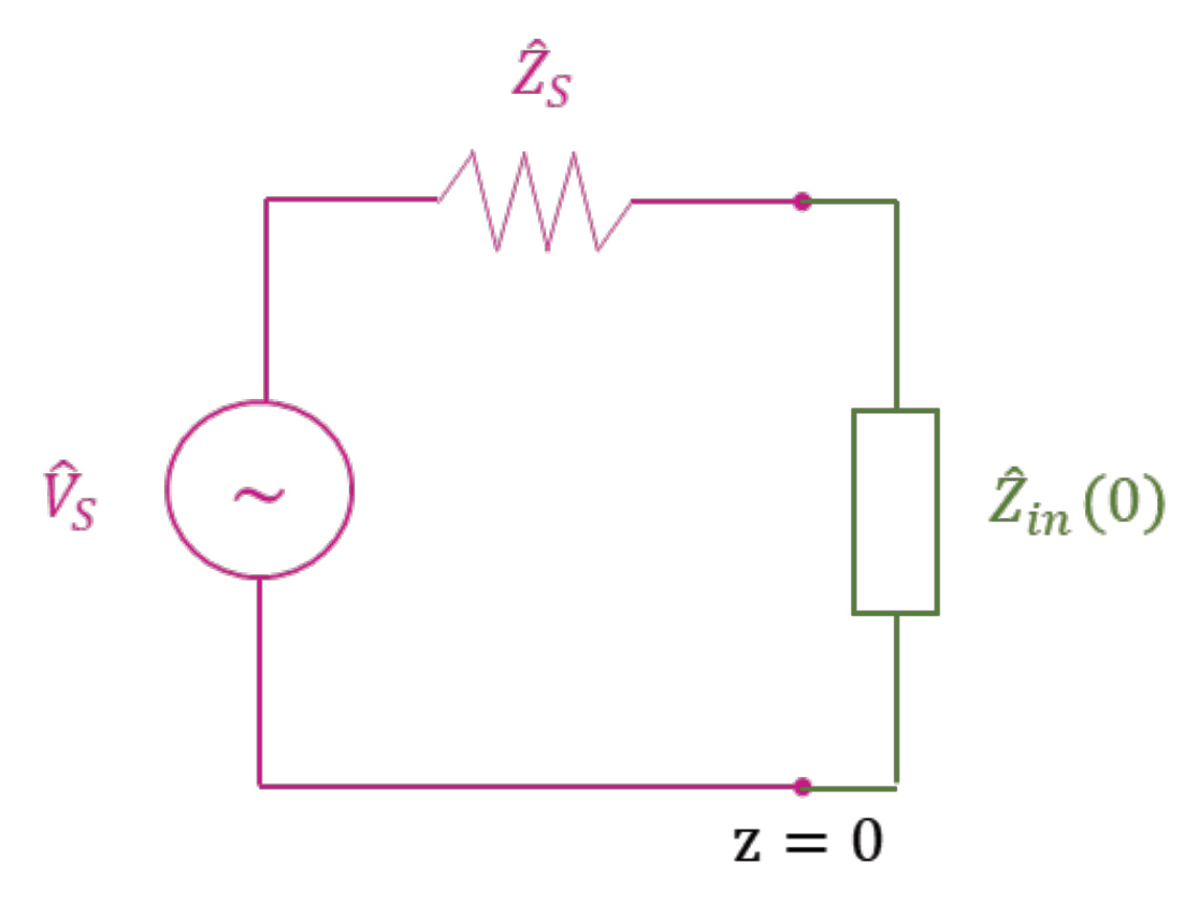
The input impedance can be calculated at any location, including z = 0, as shown in Figure 7.
We refer to this impedance as the input impedance to the line at the input to the line.
The next article will be devoted to the calculation of the input impedance at the input to the line and at any location between the source and the load.
References
- Adamczyk, B., “Concept of a Phasor in Sinusoidal State Analysis,” In Compliance Magazine, December 2022.
- Adamczyk, B., Foundations of Electromagnetic Compatibility with Practical Applications, Wiley, 2017.
- Adamczyk, B., “EM Waves, Voltage, and Current Waves,” In Compliance Magazine, April 2021.
- Ulaby, Fawwaz, et al., Fundamentals of Applied Electromagnetics, 7th Ed., Pearson, 2014.

