

his article discusses the impact of a solid conducting shield on the electric and magnetic fields when a normally incident uniform plane wave penetrates it. The shield is made of a good conductor with no aperture and a thickness much greater than the skin depth at the frequency of interest. A good conductor is defined as a medium in which the conduction current density is much greater than the displacement current density, or equivalently, the loss tangent of a medium (σ ⁄ ω >> 1). [1] Plane wave shielding is achieved with enclosures that are located far enough from the source to be in the far field where the ratio of the electric and magnetic field amplitudes approximately equals to the intrinsic impedance of free space (η0 ≅ 377Ω). Examples of this type of shielding may include fixed or mobile installations of electronics protected from airborne or terrestrial sources. A specific example of this shielding approach is when lighting electronics kept at the top of a stadium light pole are enclosed in a shielded box. This shielding box is located far from a source, such as Wi-Fi used in the stadium, and is therefore considered to be in the far field.
A uniform plane wave is normally incident on its left interface. Uniformity assumption together with normal incidence implies that the shield is in the far field of the radiation source.
The incident wave, upon arrival at the leftmost interface  , will be partially reflected
  and partially transmitted
 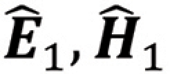 through the left interface of the shield. Subsequently, the transmitted wave will be partially reflected
 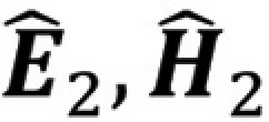 and partially transmitted
  through the right interface of the shield [2, 3].
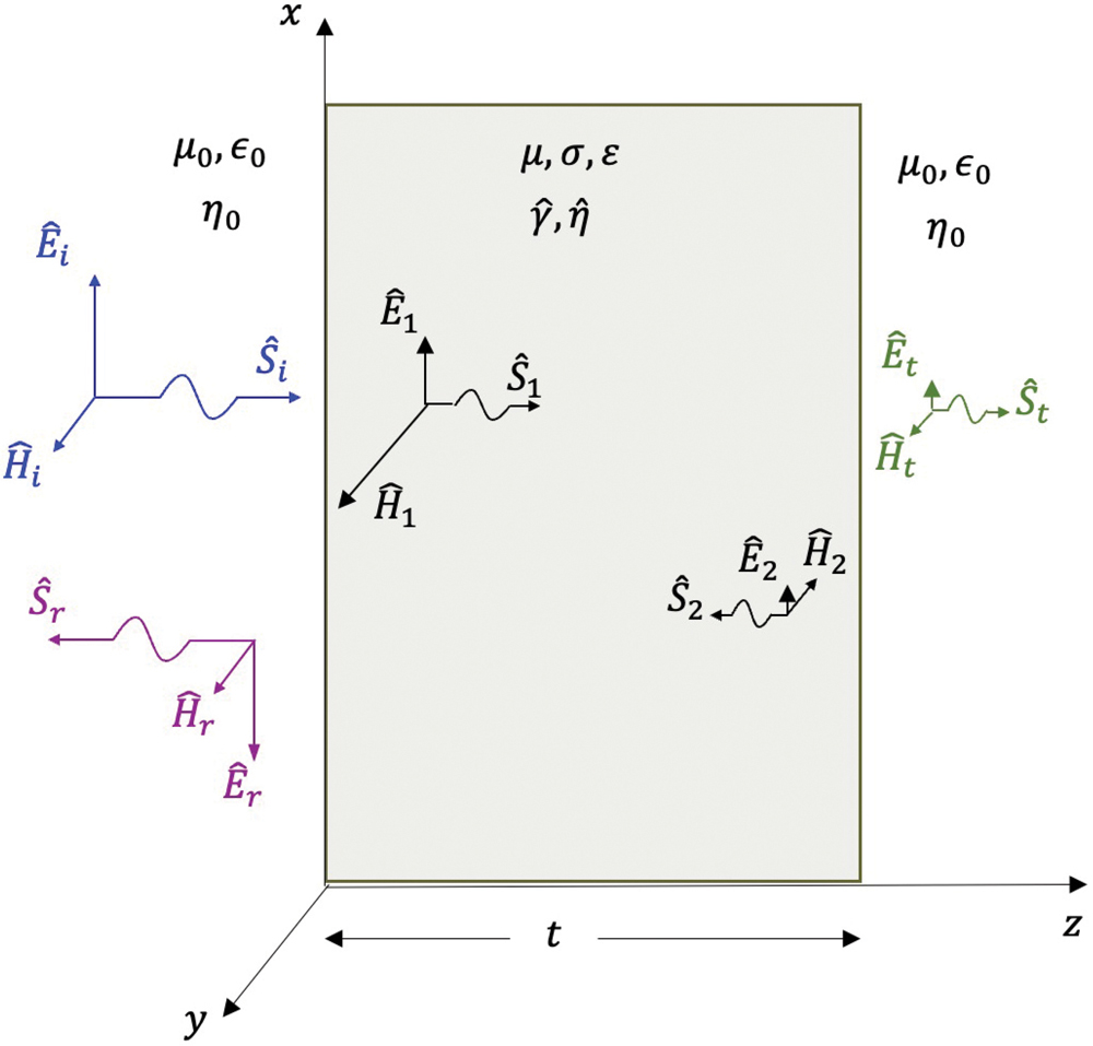
 ). This direction, ak, is determined by the directions of the electric field, aE, and the magnetic field, aH, according to the cross product as
 r is related to the magnitude of the incident electric field i by



 << η0 and the reflection coefficient at the left interface approximately equals
The total electric field at the left interface is

Very little of the electric field penetrates the left interface of the shield. Effectively, a shield consisting of a good conductor almost entirely “shortens out” the electric field. Still, a small portion of the electric field, 1 , penetrates the shield and travels through it to reach the right interface.
We will discuss the shield impact and the right interface impact on 1 shortly. For now, let’s look at the transmission coefficient at the left interface.
The magnitude of the transmitted electric field 1 is related to the magnitude of the incident electric field 1 by

 1 travels through the shield towards the right interface. Upon reaching the right interface, it gets reflected 2 and transmitted t . If the shield is several skin-depths thick at the frequency of interest (t >> δ), then the field 1 is greatly attenuated when it reaches the right interface.
The reflection coefficient at the right interface is
 2 is approximately equal to the incident field 1. As the reflected field travels back to the left interface, it gets attenuated again. Since the 1 field was greatly attenuated when it reached the right interface, the 1 field will again be greatly attenuated upon reaching the left interface and thus can be disregarded (under the thick shield assumption).
The total field at the right interface is
 1 field is greatly attenuated when it arrives there.
Continuity condition at the right interface requires

 1 is doubled in magnitude when it is transmitted through the right interface of the shield. Even though 1 doubles in magnitude, it is of little consequence since it has been greatly attenuated when traveling through the shield.
Let’s look at the transmission coefficient at the right interface. The magnitude of the transmitted electric field t is related to the magnitude of the incident electric field 1 by


- Most of the electric field is reflected at the conducting shield interface, regardless of its thickness. Thus, the primary requirement is that the shield is made of a good conductor.
- The secondary requirement is that the shield is much thicker than the skin depth at the frequency of interest.
 t is related to the magnitude of the incident magnetic field i by







Continuity condition at the left interface requires


Substituting this result into Eq. 3.9, we obtain



Let’s return to the 1 field. As this field travels through the shield towards the right interface, it is attenuated. Upon reaching the right interface, it gets reflected 2 and transmitted t .
The transmission coefficient at the right boundary is




The continuity condition at the right interface requires





- Little of the magnetic field is reflected at the left shield interface. Most of it gets doubled and transmitted through the left interface. Thus, the primary requirement is that the shield is much thicker than the skin depth at the frequency of interest.
- The secondary requirement is that the shield is made of a good conductor.
For the electric field, material conductivity is of greater importance than the thickness of the shield. Shield material does not have to be perfectly (or almost perfectly) conducting as long as the charges can redistribute themselves fast enough to create a reflection that cancels the incident wave, [4]. Most of the field is reflected at the left interface regardless of shield thickness, with thickness playing a secondary role in attenuating whatever small portion penetrates. For the magnetic field, the priorities reverse. Because the field largely passes through the left interface—doubling in magnitude as it does—thickness is the primary requirement, with conductivity in a supporting role.
A shield that is both a good conductor and substantially thicker than the skin depth at the frequency of interest satisfies the dominant requirement for each field component, providing reliable protection against a normally incident uniform plane wave.
- Bogdan Adamczyk, Peter Reiser, and Scott Mee, “Shielding Effectiveness – The Impact of Loss Tangent on the Reflection and Absorption Losses,” In Compliance Magazine, June 2026
- Clayton R. Paul, Introduction to Electromagnetic Compatibility, Wiley, 2006.
- Bogdan Adamczyk, Principles of Electromagnetic Compatibility – Laboratory Exercises and Lectures, Wiley, 2023.
- Todd H. Hubing, Electromagnetic Compatibility Course Notes, LearnEMC, 2026.

Dr. Bogdan Adamczyk is professor and director of the EMC Center at Grand Valley State University (http://www.gvsu.edu/emccenter) where he performs EMC educational research and regularly teaches EM/EMC courses and EMC certificate courses for industry. He is an iNARTE-certified EMC Master Design Engineer. He is the author of two textbooks, “Foundations of Electromagnetic Compatibility with Practical Applications” (Wiley, 2017) and “Principles of Electromagnetic Compatibility: Laboratory Exercises and Lectures” (Wiley, 2024). He has been writing “EMC Concepts Explained” monthly since January 2017. He can be reached at adamczyb@gvsu.edu.