


ecently, we were asked to supply a “dissipative” flooring system for an application where many experienced ESD practitioners would normally advocate for a much stronger electrical coupling to ground.
The discussion quickly narrowed to resistance numbers. The end user repeatedly emphasized that the floor simply needed to measure somewhere between 1 × 10⁶ and 1 × 10⁹ ohms. As long as the material fits within the ANSI/ESD STM 7.1 dissipative resistance category, they believed the requirement had been satisfied.
What was largely absent from the discussion was any meaningful consideration of body-voltage generation, operational footwear variability, or how the flooring system would actually behave during real-world use.
When we questioned the reasoning, we were told their technical source had warned that a more conductive floor could “zap” sensitive devices during handling. The statement was confidently delivered, but the underlying circuit analysis was less convincing.
It was also a nearly perfect example of how easily resistance measurements, grounding concepts, and charged device model (CDM) physics can become unintentionally disconnected from the actual discharge circuit.
Part of the confusion is understandable. Engineers are trained to believe that resistance influences current flow and discharge behavior. The misconception arises when resistance alone is assumed to define the behavior of a CDM event without closely examining the actual discharge geometry, local body capacitance, and nanosecond timescale of the initial device‑to‑hand interaction.
This article explores a common misconception in ESD flooring discussions: the belief that personnel who are too effectively grounded can increase the risk of damaging a static-sensitive device during a charged device model (CDM) event.
In electrostatics, explanations that sound convincing are not always supported by the actual circuit behavior.
One persistent example is the belief that increasing floor resistance into the dissipative range improves protection against CDM events because it “slows the discharge.” That reasoning comes from a familiar concept: higher resistance can slow current flow. In some applications, that is true and useful.
CDM events involve a very different type of circuit.
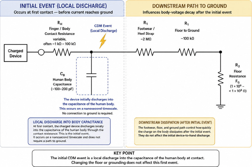
The reason is that a discharge event is not defined by earth ground. It occurs when two objects at different electrical potentials come into contact.
In CDM, the critical event occurs at the first contact between a charged device and a conductive human touch point. That electrical path is established immediately and develops on a nanosecond timescale. The flooring system is part of the overall grounding system, but it exists electrically downstream of that initial interaction.
This is where the misunderstanding often begins. It is easy to assume that any resistance in the path will influence the event. In reality, the initial discharge is governed primarily by the local interaction between the device, the person, and the capacitance of the human body.
As early as 1980, Bossard, Chemelli, and Unger at Bell Laboratories examined failures caused by triboelectrically charged devices discharging through low-impedance paths. Their work remains remarkably relevant because it focuses on the actual discharge event itself.
One important observation from their study was that grounding a metallic surface through a resistor did not necessarily control the initial fast discharge. The capacitance of the surface itself behaved as an effective local ground during the transient.
In practical terms, the immediate discharge geometry and local capacitance dominated the first event long before downstream resistance had much influence.
At the moment of first contact, the governing elements are:
- The charged device;
- The conductive contact point of the hand; and
- The capacitance of the human body
The footwear-floor-ground pathway exists electrically downstream of that interaction. It can influence how quickly charge dissipates afterward, but it does not define the initial discharge event.
Put simply: If the flooring system is not part of the first discharge path, it is not controlling the first discharge event.
Flooring plays a critical role in controlling body voltage by:
- Reducing triboelectric charge accumulation during movement;
- Supporting charge dissipation through footwear systems;
- Helping stabilize personnel voltage during operation; and
- Supporting grounded carts, chairs, and mobile equipment.
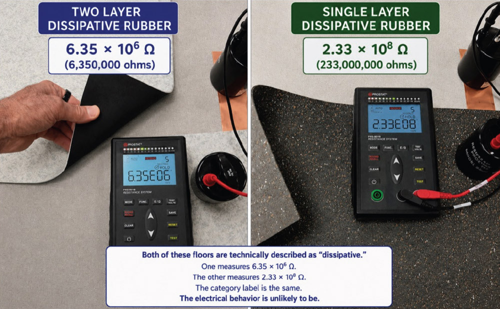
Another source of confusion is the extraordinary breadth of what the industry defines as “dissipative.” Under ANSI/ESD terminology, the dissipative range spans from 1 × 10⁶ ohms to < 1 × 10⁹ ohms.
Mathematically, that is a very large range.
A flooring material measuring 2 × 10⁶ ohms and another measuring 9 × 10⁸ ohms may both be classified as dissipative while behaving very differently in terms of body-voltage control.
For that reason, selecting a floor simply because it is labeled “dissipative” can become misleading. The category alone does not describe how the flooring system will behave under real operational conditions.
A more useful question is “How effectively does the entire flooring system control body voltage during actual use?”
This also helps explain why, within reasonable engineering limits, stronger electrical coupling to ground generally improves personnel voltage control.
A flooring system with stronger coupling to ground will typically:
- Dissipate body charge more effectively;
- Maintain lower personnel voltage;
- Broaden the range of controlled footwear capable of acceptable performance; and
- Reduce the likelihood of excessive charge accumulation before contact.
- Allow greater body-voltage buildup;
- Slow charge decay;
- Narrow acceptable footwear conditions; and
- Increase dependence on strict procedural compliance.
Effective CDM mitigation begins by reducing the creation, accumulation, and transfer of unwanted charge throughout the process.
The most effective way to reduce device-to-person CDM events is often to prevent significant charge from developing on the device in the first place. If the device never becomes meaningfully charged, the probability of a damaging discharge event drops dramatically.
In practical terms, sensitive devices should ideally remain grounded, referenced, or otherwise prevented from developing excessive charge before handling occurs.
This is why effective CDM control usually depends less on attempting to influence the discharge after it begins and more on preventing excessive charge generation upstream of the event.
The flooring system plays an important role in that process because it strongly influences how effectively body charge dissipates during normal movement and operation.
A flooring system measuring on the order of 10⁵ ohms point-to-ground or point-to-point is not equivalent to a metallic short circuit. It is still a controlled resistance path, but one that is substantially more effective at dissipating body charge and controlling personnel voltage than flooring systems approaching the upper end of the dissipative range.
In practical operation, there is a significant electrical difference between a floor measuring 106 ohms and one measuring 10⁸ ohms, even though both may be casually grouped within the broad ANSI/ESD dissipative resistance category.
A competent assessment may evaluate whether:
- Sensitive devices are becoming triboelectrically charged during handling or transport;
- Packaging materials are generating charge;
- Whether dissipative work surfaces are being properly implemented;
- Devices are unnecessarily isolated from grounded or static-safe surfaces;
- Carts, fixtures, conveyors, or automation systems are generating unwanted charge;
- Induction effects are charging devices without direct physical contact;
- Personnel grounding systems are maintaining acceptable body voltage during actual operation;
- Ionization may be appropriate in areas where charge generation cannot reasonably be eliminated; or
- Process materials or environmental conditions are contributing to unnecessary charge accumulation.
Intermittent charge generation or isolated discharge events within automated equipment may not be obvious during routine inspection or resistance testing alone. In these situations, experienced ESD investigators may utilize charge-event detectors and related diagnostic methods to identify hidden charging mechanisms or isolated discharge locations within the process.
In complex automated systems, multiple detectors may sometimes be used to help localize or triangulate the origin of intermittent events that would otherwise remain difficult to identify.
All of this illustrates why effective CDM control is fundamentally a process-engineering and root-cause-analysis discipline rather than simply a flooring-resistance discussion.
This is one reason organizations such as the ESD Association (ESDA) play such an important role in advancing the theory and practice of electrostatic control.
Electrostatics depends on how circuits actually behave in the system, not simply on how resistance categories are interpreted.
Advancing ESD control requires continual re‑examination of assumptions against measured operational behavior, real-world charge generation, and the physics of the actual event.
- A charged object can discharge into a grounded object.
- A charged object can discharge into a floating object.
- Grounded versus floating does not determine whether a discharge occurs.
- The voltage difference at the moment of contact defines the event.
- That is the part of the system that is often overlooked.
- Bossard, P. R., Chemelli, R. G., and Unger, B. A., Bell Laboratories, “ESD Damage from Triboelectrically Charged IC Pins,” 1980.
- ANSI/ESD STM7.1-2020, Flooring Systems Resistive Characterization, EOS/ESD Association, Inc., 2020.
- ANSI/ESD STM97.2-2016, Floor Materials and Footwear — Voltage Measurement in Combination with a Person, EOS/ESD Association, Inc., 2016.

David Long is the CEO and founder of Staticworx, Inc., a U.S. leader in static‑control flooring for mission‑critical environments. Drawing on more than 30 years of work in electrostatics, flooring systems, and concrete-substrate diagnostics, Long advocates a systems-based approach to ESD control focused on real-world operational behavior, hidden sources of electrostatic risk, and long-term system reliability. His work helps organizations design more robust electrostatic control infrastructure for environments ranging from semiconductor manufacturing to critical operations centers. Long can be reached at dave@staticworx.com.