
he ubiquitous 41” rod antenna has been used to measure electric fields below 30 MHz for over seven decades. Most EMC engineers know that the effective height of an electrically short whip is precisely half its physical length. But the effective height or length of the 41” rod element is taken to be a half-meter. Given that a meter is not 41 but 39.37 inches, there appears to be a small discrepancy.
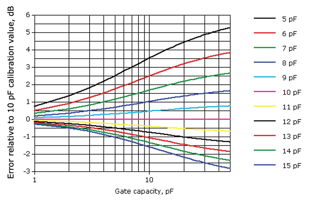
Similarly, the capacitance of a short whip is a function of both length and diameter. A capacity of 10 pf is almost universally used for the 41” rod element, but in fact, that is the capacity of a one-meter length whip with 1/8” diameter. Since rod elements are 41” and range in diameter from around ¼” to a centimeter or more, depending on manufacturer, the capacity is always higher than 10 pF.
If these conundra have had the reader tossing and turning, lying awake at night, reading this short article will reveal the historical reason behind the disparities, and that, while the history is interesting, the disparities do not significantly affect measurement accuracy. Having read this very short article, the reader will be better informed, his concerns will be allayed, and he can rest easy.
A small consulting job recently brought to the author’s attention that the latest revision of SAE ARP-958 lists the effective height of the 41” rod antenna not as the traditional 6 dB below one meter but instead as 5.6 dB below one meter.1 This is based on using the 41” (1.04 m) length as opposed to precisely one meter, the latter having been the custom for seventy years, even including previous revisions of ARP-958, going back thirty years.
There are two interrelated aspects to this: one trivial and the other more interesting.
The trivial aspect is that if one is computing to the nearest centibel in a field of endeavor where +/- 3 decibels is a holy grail, at least do it right. Compute in millibels and round off to the nearest centibel:
he = 20 log (physical length/2) = 20 log (1.0414 m / 2) = -5.668 dB meter
The more interesting question, though, is why have we used a 41” rod element all this time and always approximated the effective height as one‑half meter. While the 0.3 or 0.4 dB error is truly minor (unless one is enamored of centibels), it would have been just as easy to have a one-meter-long element instead of 41 inches.
To answer this question, we have to step into the EMI testing way-back machine, conveniently located on the premises of the Museum of EMC Antiquities.
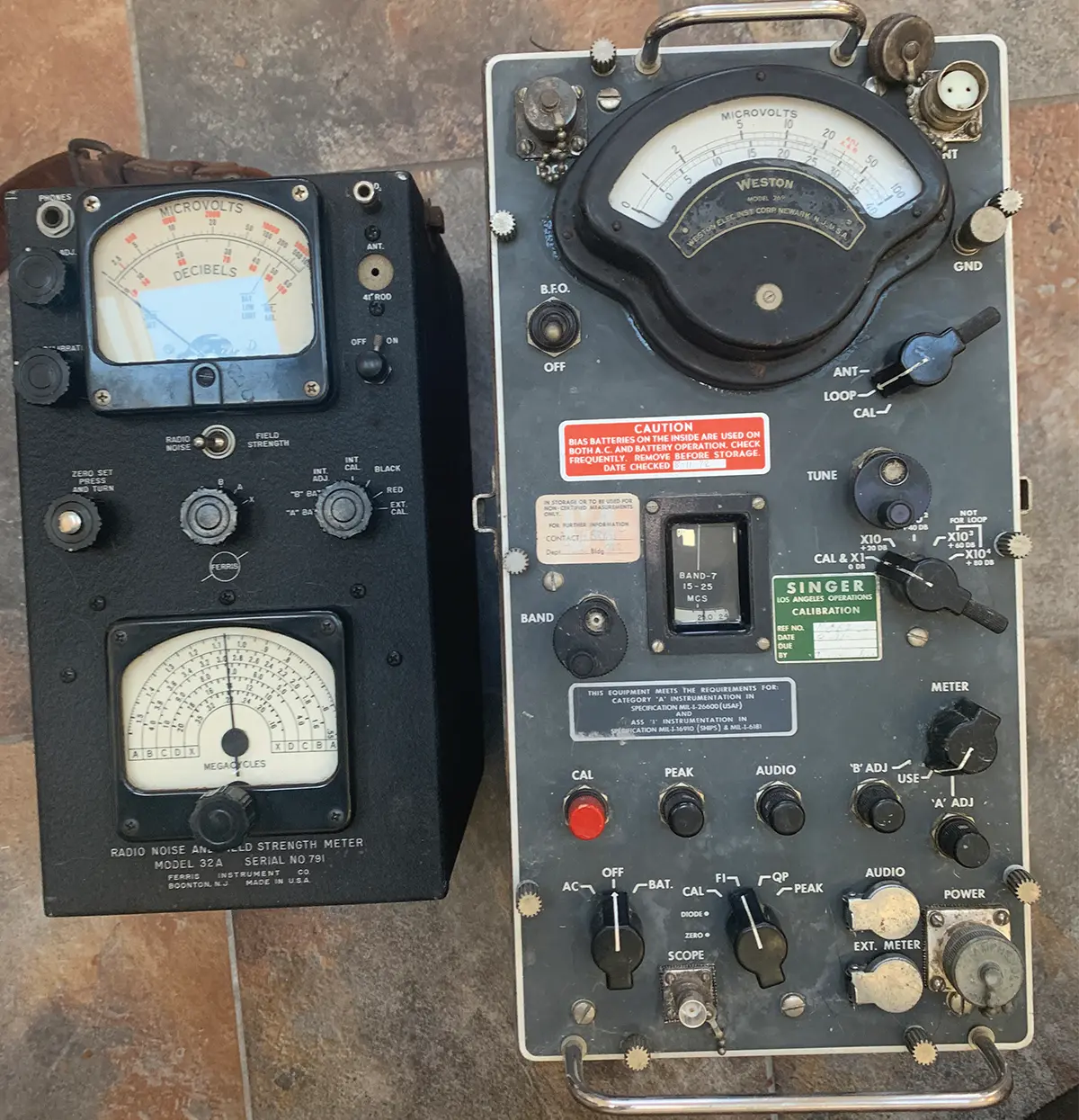
We turn the dial back some 90 years to the development of the Ferris Model 32 Radio Noise and Field Strength Meter (see Figure 1) and first offered for sale in 1932.2 This radio frequency voltmeter had a frequency range of 150 kHz to 20 MHz, less 200 kHz between 350 – 550 kHz, using five different octave tuning bands.
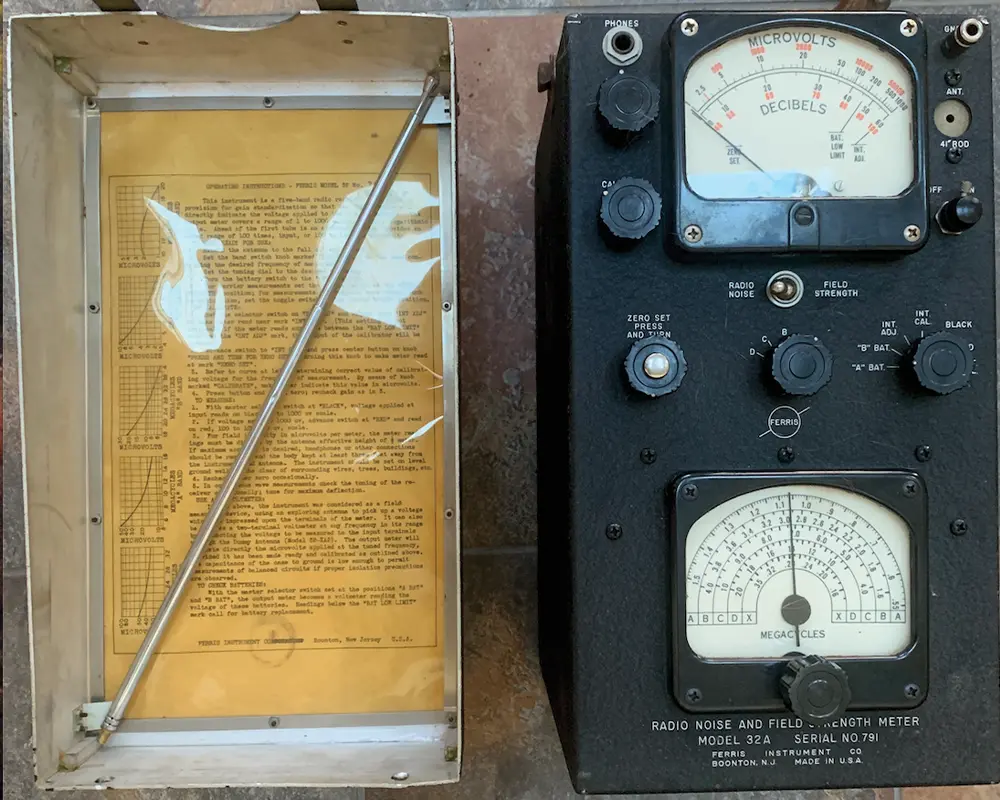
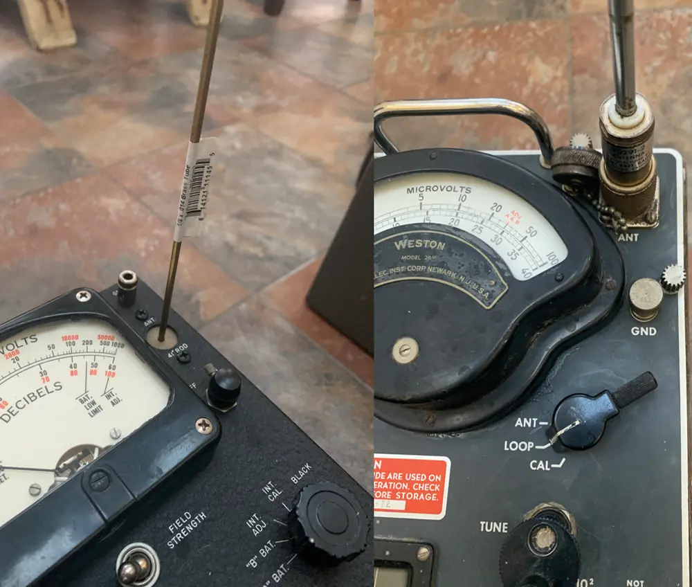
Figure 2 portrays side-by-side images of the 1930s‑era Ferris 32A and the 1950s‑era Stoddart NM-20 receiver that eventually replaced it, showing both antenna ports (a) and antenna connections (b).4 We can see that both are outfitted with a rod element. The difference is this. The (supplied) Ferris element was a 41” long 1/8” diameter collapsible Monel rod with no connector at the base. It simply slid into a hole in the faceplate of the Ferris Model 32.5 The depth of the hole was 1.5”, leaving 39.5” above the faceplate. Compare that to 39.37” per meter, and the 6 dB (5.99 for millibel fetishists) effective height factor becomes apparent.

As soon as the AN/PRM-1 became available commercially, it shows up in the standards as the primary choice to be used below 20 MHz, with the Model 32 reclassified as acceptable under certain circumstances. This was due to the AN/PRM‑1 including a peak detector, which the earlier Ferris model lacked. But since the AN/PRM-1 was, in fact, designed to replace the Ferris Model 32, it had to include a 41” rod antenna.
The “mistake” made by Stoddart and all who followed was to copy the 41” but put all of it above a connector that protrudes from the top of the meter or antenna base (Figure 3). Of course, there was nothing stopping anyone from collapsing the rod element to precisely one meter, but with few exceptions, that wasn’t mentioned or required in standards and, therefore, wasn’t done.7,8,9

Some might consider the use of the term “approximately” in a contractual specification as less than ideal. But fortuitously, this “closes the loop,” tying the first issue of centibel hair-splitting to the second of whence the 41” long “meter.”
The Ferris Model 32 instruction manual on the topic of splitting decibels explains the proper use of significant figures:
Also, compare the cited +/-10% amplitude tolerance value (+0.8 – -0.9 dB) to the MIL-STD-461 +/- 2 dB requirement for a measurement receiver. And +/- 2 dB is still representative of total amplitude measurement accuracy of the latest EMI receivers as of this article’s publication.

Until now.
- SAE ARP-958E, “Electromagnetic Interference Measurement Antennas; Calibration Method” (2021)
- Parker, A. T. “A Brief History Of EMI Specifications,” Presented at the 1992 IEEE EMC Symposium.
- The Model 32 instruction manual barely mentions the application of measuring interference, and not at all with respect to the use of the 41” rod antenna. The Model 32 was envisioned as being used to map field contours of broadcast radio station antennas, and the manual goes into considerable detail on how to do that.
- The AN/PRM-1 manual, by contrast mentions interference measurement first, and then mapping broadcast fields, and then as a microvoltmeter.
- Two items of importance. In the Ferris meter, the cutout around the 1/8” diameter shaft is not metallic, but plastic. It serves the same purpose as the cutout at the top of a modern-day 41” rod antenna: to avoid shunt capacitive loading of the rod’s output. Second, the museum’s Model 32 is missing the original collapsible rod. Museum personnel followed the manual’s instructions that a 1/8” diameter rod or pipe of brass or other metal could be substituted if the collapsible rod wasn’t available.
- See for example, MIL-I-6181B “Military Specification: Interference Limits, Test and Design Requirements, Aircraft Electrical and Electronic Equipment,” dated 29 May 1953. Figure 15 is a fully dimensioned, build-to-print level of detail drawing for a Ferris meter connection to provide a 50 Ω termination while interrogating a 5 uH LISN.
- MIL-I-16910A dated 1954, “Interference Measurement, Radio, Methods and Limits; 14 Kilocycles to 1000 Megacycles”
- MIL-STD-826, “Electromagnetic Interference Test Requirements and Methods,” dated 20 January, 1964 refers only to “1/2 meter rod (electrical length = 1/2 meter), not a 41” rod antenna.
- MIL-STD-461A, “Electromagnetic Interference Characteristics Requirements for Equipment…” dated 01 August 1968, refers to “a 41-inch rod antenna (electrical length = 0. 5 meter).”