n past articles, we’ve discussed troubleshooting techniques for dealing with radiated emissions. Let’s turn our attention towards performing our own radiated emissions pre-compliance testing in-house.
The purpose of pre-compliance testing is an attempt to duplicate the test setup as used by your third-party test lab (Figure 1). Because these test chambers are fully shielded and lined with expensive ferrite and carbon-loaded RF absorber material to reduce reflections, they can cost several million dollars to construct.

Ideally, you should procure a copy of the appropriate EMC test standard used, depending on the product type. For example, for military testing, you’ll need a copy of MIL‑STD-461. For commercial, industrial, or medical products, you’d use one of the IEC standards, such as IEC/EN 61326, IEC/EN 60601, or the generic IEC/EN 61000-6-3, which will refer back to CISPR 11 or CISPR 32. For automotive modules, you’ll need a copy of CISPR 25. These will describe the equipment and setups and test limits required.
I’ve listed many choices of analyzers and antennas in volume 1 and standards and test setups in volume 2 of my EMC Troubleshooting Trilogy (Reference 1). Figure 2 shows a popular example of an affordable bench top spectrum analyzer.
Figures 3, 4 and 5 show example antennas.


You’ll find the larger EMI antennas to be more sensitive in the frequencies below 300 MHz. This is helpful, because we’ll often see emissions in the 50 to 300 MHz frequency band.
Some of the physically smaller antennas (Figure 4), may work at a 1 or 3m test distance, but probably not at 10m due to lack of sensitivity.
If you’ve no room to store one of the larger full-sized EMI antennas, then you might consider a broadband active antenna in Figure 5. A built-in RF preamplifier brings the sensitivity up to about the same as a full-sized EMI antenna. I’m currently using this antenna because it packs up nicely in a small transit case. I’ve compared the performance of these three antennas in Reference 2.
Often, you’ll also require a 20-dB broadband RF preamplifier in order to boost the signals to a useable level. Some analyzers may have this capability built-in, though.
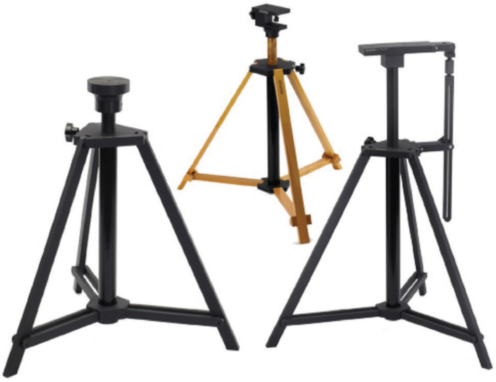
One last item you’ll need is a sturdy antenna tripod. Several companies make these and I describe several in volume 1 (Reference 1). For the larger antennas, see examples of heavy-duty tripods in Figure 6. Lighter antennas can use a lighter tripod. Check volume 1 of my trilogy for many more choices.

I’ve found conference rooms work pretty well. They are out of the weather, resources are usually close at hand, and it’s easier to clear out an area to test. Figure 8 shows one of my early setups while testing an industrial alarm system at the client’s facility. Notice the client constructed a wooden turntable, which allowed rotation of the product under test to find the maximum emission.


Next time, we’ll discuss the details of making the measurement and add some additional examples of successful test locations and setups.
- Wyatt, EMC Troubleshooting Trilogy.
- Wyatt, “Evaluating Reduced-Size EMI Antennas – Part 1,” EDN.