ince the first observations of interference from unknown events with AM radios in the early 1920s, the field of electromagnetic interference (EMI) has continued to evolve and involve more than AM radios. Today, any product with a power cord or that is battery-operated can and will generate electromagnetic fields. Electromagnetic compatibility (EMC) testing is required for any product that has electrical, digital, and/or radio components.
With the growth of the variety and volume of those products, the time to complete EMC testing typically takes longer, due to competition for lab time, and for surprises in tracking down short-burst or impulse-type emissions. The automotive industry, for example, requires exacting methodologies to measure all emissions accurately. Long test times impact test facility availability and potentially reduce the number of devices that are certified. It’s also easy to miss intermittent disturbance signals with conventional scans since an extended dwell time must occur at each frequency.
With the implementation of time domain functionality in EMI receivers and short-time FFT (STFFT) engines, EMI receivers now enable independent compliance test laboratories and in-house certification labs to shorten their overall test time, and for device manufacturers to quickly troubleshoot intermittent and impulse signals during design validation and pre-compliance testing.
This article will provide a short history of radiated EMI testing, a discussion on the evolution of EMI receiver designs, and a look at the newer time domain scan and FFT capabilities to meet EMI measurement requirements. We’ll also discuss EMC standards such as CISPR 16-1-1 and MIL-STD-461 and highlight how you can easily reduce receiver scan and test time from multiple hours to seconds. Finally, we’ll identify those areas where this makes the biggest difference, and when you may not need to consider adapting the newer technology.
Their work aligns with the discovery of solar activity creating “phantom telegraph operators,” in which radiated emissions are picked up by the long parallel transmission wires that generate telegraph output without telegraph input,3 as well as the growth of broadcasting and the use of electronic equipment in commercial and military applications. As a result of these developments, some sort of rules or regulations would become necessary to prevent radio interference or equipment malfunctions.
Early studies of interference tended to be called “noise,” primarily because their presence was identified as audio noise. Many attempts were made to quantify and measure this noise so that measurement techniques and limits could be established. But getting agreement with different measurements proved difficult, in part due to the concern being limited to an “annoyance factor,” that is, how the noise or interference “annoyed” the intended transmission or product use. The consensus was that high-repetition noise was more annoying than low-repetition noise. This ultimately led to the development of radio noise, objective sound meters, and quasi-peak detectors.7

Figure 2 shows the typical architecture for a traditional swept spectrum analyzer. Developments of stable local oscillators that could be swept allowed for fast, continuous tuning and measurements across the defined frequency range. Note that there is typically a pre‑selector or low-pass filter before the first mixer. This allows for a lower noise floor for the measurement and prevents broadband signals from overdriving the mixer.


The high band path has a Yttrium Iron Garnet (YIG) swept preselector to protect the first mixer and resembles the traditional swept spectrum analyzer architecture. The bandwidth of the YIG preselector is much narrower than the RF preselector in the low band path, which ensures the dynamic range required at the higher frequencies.
Figure 4 shows the analog IF section replaced with a digital section. After the down conversion, the signal is converted to a digital value, which is a digital amplitude value. The term “digital IF” describes the digital processing that replaces analog IF processing found in traditional receivers and spectrum analyzers.9

Table 1 shows a typical comparison of the differences in amplitude uncertainties between digital and analog IF sections. The data represented here was collected by surveying receiver and spectrum analyzer specification guides.10
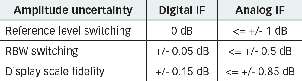
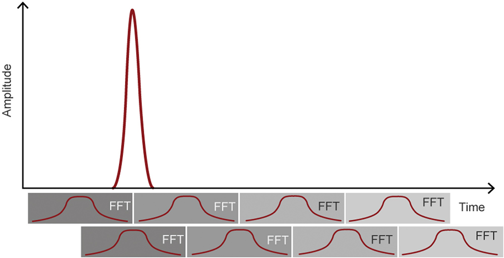
Figure 5 shows an example of measuring an impulse signal with 50% overlap. In this scenario, the second FFT frame (bottom row) gives a full response because the impulsive envelope occurred at the time of maximum weighting.11 With 90% overlap, the worst-case error from the windowing occurs when the envelope peak is displaced from the weighting peak by 5% of the FFT duration.

- Faster measurement times: Because the overlapping FFTs allow you to capture broadband signals in one dwell time, the measurement time is much faster than the traditional swept frequency receivers. Table 2 shows the dramatic difference in measurement times for a typical automated broadband noise test.
- Impulsive noise detection: If your equipment under test (EUT) has impulse noise contributors, or if you need to investigate if it has those characteristics, then the FFT capability may be the only way to capture that phenomenon.
Figure 7 shows an example on the left of an impulsive signal (in this case, a pulsed comb generator) where the traditional stepped scan is only able to capture one of the frequencies, vs. the overlapped FFT on the right, where all frequencies are captured on one acquisition.
- Unique EUT characteristics: If your EUT has unique characteristics (for example, it is not able to be left in a powered on condition for a complete test, or it has motors or switches that operate normally during the use of the product such as pumps or motor drives in a washing machine), then you would benefit from FFTs being able to capture the emissions when the EUT is exhibiting one of those emissions.
- Exhaustive pre-compliance validation: If you wish to exhaustively test your EUT for pre-compliance for any impulsive surprises, then the overlapping FFTs will allow you to detect those before you send it to the test lab for final compliance tests.


Some CISPR standards for specific device types may not allow for the use of FFTs for compliance measurements. You will need to review the CISPR standard applicable to your EUT to determine if that edition is referenced in your standard to decide whether FFT measurements are allowed for full compliance testing.
- Thomas S. W. Lewis, Empire of the Air, 1991, Harper Collins Publishers.
- Ibid., page 40.
- Gubisch, R., Holz, B., “The Engineer’s Guide to Global EMC Requirements: 2007 Edition,” pp. 2, Intertek, 2007.
- Mohd Fahmi, Abdul Rahim, Agilent Technologies, Inc., “Evolution and Trends of EMI Receiver,” 2013 IEEE International RF and Microwave Conference, Penang, Malaysia.
- CISPR, Wikipedia, https://en.wikipedia.org/wiki/CISPR.
- Federal Communications Commission, Wikipedia, https://en.wikipedia.org/wiki/Federal_Communications_Commission.
- Burrill, C.M., “Progress in the Development of Instruments for Measuring Radio Noise”, Proceedings of the IRE, vol. 29, issue 8 pp. 433‑442, August 1941.
- Houck, H. W., “The Armstrong Super-Autodyne Amplifier, part 1,” Radio Amateur News, Experimenter Publishing Co., New York, vol. 1, no. 8, February 1920, p. 403.
- Thomas S. W. Lewis, Empire of the Air, 1991, Harper Collins Publishers, Chapter 6.
- Keysight Technologies, “Enhance EMC Testing with Digital IF – Application Note,” June 18, 2015.
- Ibid.
- Keysight Technologies, “Boost EMC Test Throughput with Accelerated Time Domain Scan,” July 14, 2023.