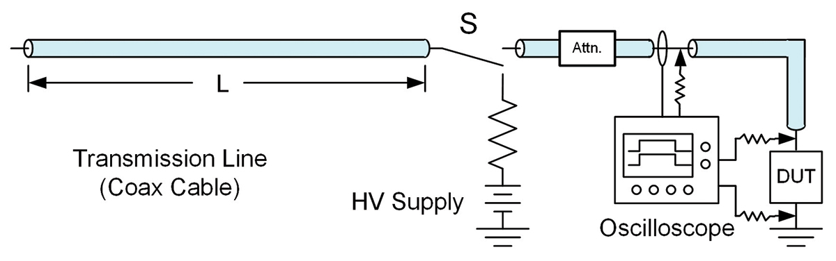
Variable contact resistance in time domain reflection TLP, especially in wafer-level measurements, can introduce significant noise into voltage data. This is compounded in vf-TLP when two large voltages need to be subtracted to get the device under test (DUT) voltage. These issues can be reduced significantly using Kelvin TLP. In Kelvin TLP, the voltage is measured with voltage taps right at the DUT. For waferlevel measurements, this requires a separate set of RF probes with appropriate sense resistors. Kelvin measurements can be used for either 100 ns or vf-TLP. For 100 ns TLP a current probe is needed to determine the pulse current. For vf-TLP, a separate voltage pickoff Tee is often used to measure the separated incident and reflected voltage to calculate the stress current. In addition to reducing voltage noise, Kelvin TLP gives a direct measurement of the voltage versus time characteristics of the DUT without the uncertainty introduced by time-shifting the incident and reflected voltage pulses.
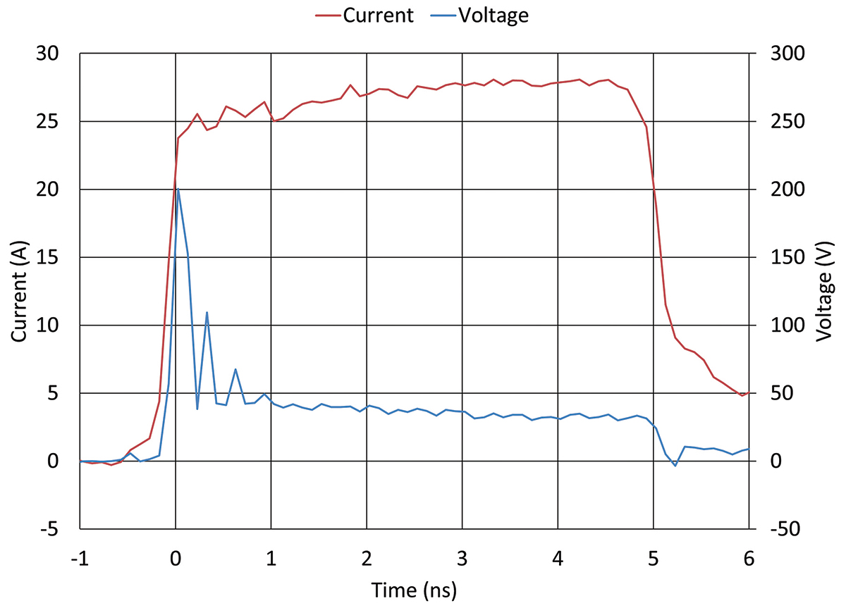
An example of the time dependence of a 28 A vf-TLP pulse is shown in Figure 2 for a low capacitance transient voltage suppressor (TVS). The 5 ns long current pulse is well-formed with a rise time of a small fraction of a ns. The TVS device clamps the voltage to below 5 V within 1 ns. There is, however, a voltage overshoot of about 20 V. Measurements like this give considerable insight into the properties of devices in the ESD time and current regime.
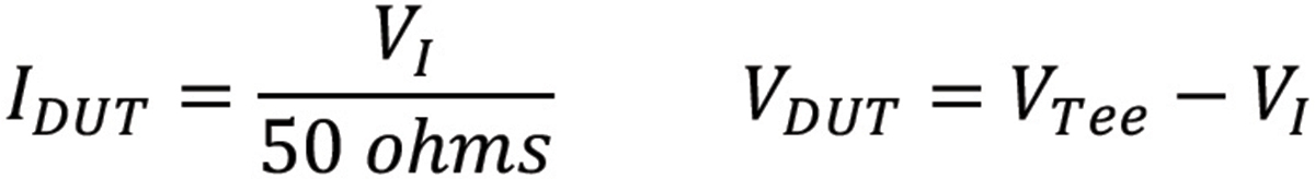
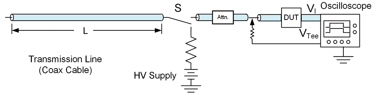
The time domain reflection and transmission (TDRT) TLP system, shown in Figure 3, provides a direct measurement of the current. In this system, the DUT is inserted in line between the pulse source and the oscilloscope 50-ohm input, rather than between the pulse source and ground. The device current and voltage are calculated with the following formulas where VI is the voltage measured on the current measuring channel of the oscilloscope, and VTee is the voltage measured on the voltage pickoff Tee. In vf-TLP, it will likely be necessary to do time shifting between the VTee and VI measurements. Depending on cable lengths, it may be necessary to time shirt VTee or VI before calculating VDUT.
The TDRT system is especially useful in situations where there is a desire to directly measure the time dependence of the current through the device. It is important to note that the TDRT system has a characteristic impedance of 100 ohms, which is the sum of the 50-ohm characteristic impedance of the coaxial cable delivering the pulse and the 50-ohm impedance of the oscilloscope input. The importance of a system’s characteristic impedance will be discussed in the next section.
Another member of the TLP Zoo is the current source TLP, which is one of the original configurations introduced by Tim Maloney in 1985[2]. This method removes the reflection problem without an attenuator, as in our other examples, by incorporating a matching network just before the DUT. The importance of this method goes far beyond the method of removing reflections since it introduces a TLP system with a characteristic impedance much higher than 50 ohms. This difference can be significant for devices with deep snapback. Deep snapback is common for higher voltage protection devices.
A schematic of a current source TLP is shown in Figure 4. At the end of the cable leading to the DUT is a termination resistor and a 500 ohm or more resistor in series with the DUT. The value of the termination resistor is a compromise to give good reflection control over a range of DUT impedances.
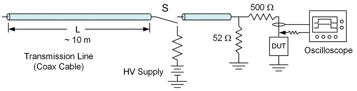
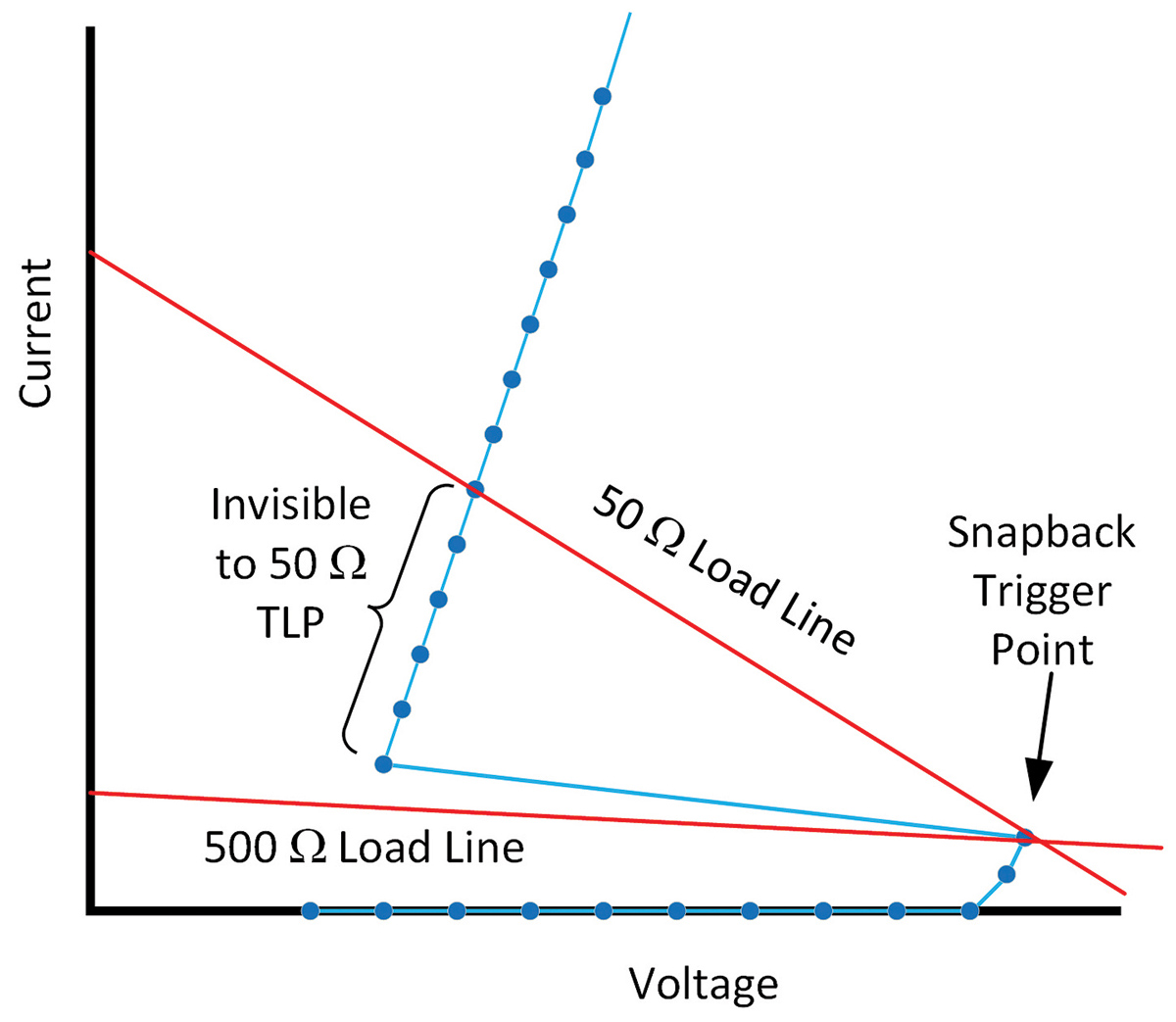
While the matching network limits the peak current for the current source TLP system, this arrangement provides a TLP system with a high source impedance. The source impedance sets the load line for a system, which is the straight line connecting the open circuit voltage with the short circuit current. The slope of this curve is one over the source impedance. For a particular TLP charging voltage, all possible current-voltage pairs must be on this line. The significance of this for TLP measurements on a snapback device is shown in Figure 5. Consider the data point which is about to trigger the device into snapback. Up to this point measurements with a 50-ohm TDR TLP or a 500-ohm current source TLP will give the same results. In Figure 5, the load lines for a 50-ohm and a 500-ohm TLP system are drawn for the snapback trigger point. The next TLP pulse will trigger the device into snapback. The load line requires that the next data point be on the load line for the TLP system being used. For the device in question, the next possible current voltage pair for the 50-ohm TLP is well up in the device’s snapback region. For the 500-ohm system, with its shallow load line, additional measurement points can be captured in the low current snapback region. As demonstrated in Figure 5, a significant portion of the snapback region is invisible to the 50-ohm TLP. For some devices, the entire snapback region may be invisible and the first data point after the snapback trigger can cause device damage. In the case of devices that fail soon after snapback, the invisible points give valuable information on the true failure threshold level.
Field-induced CDM testing relies on an air discharge, which becomes less reproducible at low voltages. Unfortunately for the fastest interconnects and other sensitive pins accurate, and repeatable CDM testing at low voltages is becoming more important. Vf-TLP has inspired two test methods, capacitively coupled TLP (CC-TLP)[3] and low impedance contact CDM (LICCDM)[4][5], which could supplement or even replace field-induced CDM testing at low voltages.
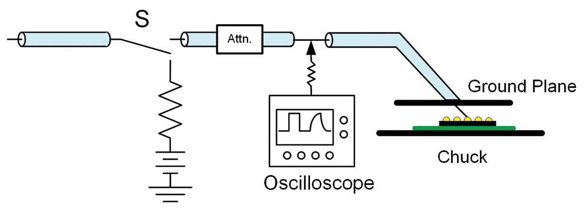
Figure 6 illustrates a capacitively coupled TLP system. The DUT is placed on a wafer chuck in either package or wafer form. A vf-TLP system provides the pulse for a specialized wafer probe. The end of the wafer probe has a ground plane tied to the shield of the pulse cable. The ground plane is placed parallel to the DUT and a small distance above the DUT. The coax cable’s center conductor is connected to a wafer probe needle which extends through a hole in the ground plane and contacts the pin under test. The capacitance between the DUT and the ground plane completes the current path between the cable center conductor and the cable shield. A voltage pickoff Tee is used to measure the incident and reflected pulses. The incident and reflected pulses are used to calculate the stress delivered to the DUT.
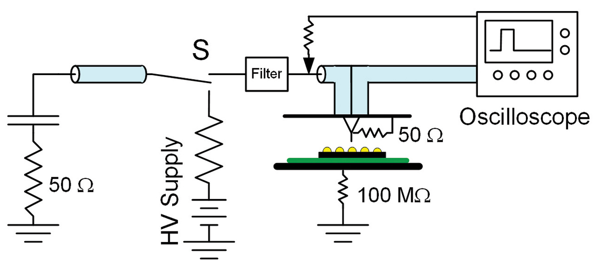
LICCDM similarly starts with a vf-TLP system as a pulse source, although this is modified with a capacitor and 50-ohm resistor at the far end of the charging cable. The 50-ohm resistor eliminates reflections, and the capacitor provides a slow decay to the trailing edge of the pulse. A rise time filter is used to adjust pulse properties to better match CDM waveform properties. The pulse is delivered through a hole in the ground plane with a pogo pin to contact the DUT. In addition to the delivery cable connected to the pogo pin, a second 50-ohm cable connects to an oscilloscope input as well as a 50-ohm resistor to ground. The two 50-ohm cables and 50-ohm resistor in parallel with each other creates a 16.7‑ohm termination, 50 ohms divided by 3. Conveniently, 16.7 ohms is similar to the source impedance of an air discharge field-induced CDM tester. The current through the DUT is calculated by measuring the pulse current while in contact with the DUT and not in contact with the DUT combined with the known 50-ohm impedance of the two cables and the 50-ohm resistor to ground.
Both CC-TLP and LICCDM produce stress currents with stress currents similar to field-induced CDM but without the reproducibility issues of air discharge. Several studies show that the failure currents and failure modes produced by CC-TLP and LICCDM are similar to failures in CDM testing. For either of these systems to become an alternative to traditional CDM will require the development of correlation methods between CDM voltage levels and the stress levels of CC-TLP and LICCDM. This work is currently underway in the joint JEDEC/ESDA CDM working group.
Electrostatic Discharge Association (ESDA) working group WG5.5 is dedicated to TLP. Their primary document is a Standard Test Method, ANSI/ESD STM5.5 [6] detailing procedures necessary for the accurate measurement of quasi‑static IV curves in both standard TLP and vf-TLP. The working group has also recently published two especially useful Technical Reports. ESD TR5.5-04‑18 [7] is a TLP User Guide giving a range of tips on how to get the most out of TLP measurements as well as examples of use of TLP. ESD TR5.5-05-20 [8] gives guidance on how to perform transient measurements, primarily using vf-TLP.
TLP has become one of the most important tools available to the ESD protection design engineer. TLP can be used to characterize both the protection circuit as well as devices needing protection. As this article has shown, there are a variety of members of the TLP Zoo, each with its own strengths and weaknesses. Today most TLP users employ commercially built TLP systems. Some systems are designed to be used in a single configuration, simplifying their operation but limiting flexibility. Other systems can be configured in multiple ways, and choosing the best configuration for each measurement is key to getting the most from the system. This article has reviewed some of the important members of the TLP Zoo and should be helpful in getting the most out of whatever system is used as well as understanding some of the limitations.
- R. Ashton, “Characterization for ESD Design, the TLP Zoo Part 2,” In Compliance Magazine, February 2022.
- T. Maloney and N. Khurana, “Transmission Line Pulse Techniques for Circuit Modeling of ESD Phenomena,” Proceedings of the EOS/ESD Symposium, 1985.
- H. Wolf, H. Gieser, W. Stadler, and W. Wilkening, “Capacitively coupled transmission line pulsing CC‑TLP—A traceable and reproducible stress method in the CDM-domain,” Proceedings of the EOS/ESD Symposium, 2003.
- N. Jack and T. Maloney, “Low Impedance Contact CDM,” Proceedings of the EOS/ESD Symposium, 2015.
- ANSI/ESD SP5.3.3‑2018, Low Impedance Contact CDM as an Alternative CDM Characterization Method.
- ANSI/ESD STM5.5.1-2016, For Electrostatic Discharge Sensitivity Testing – Transmission Line Pulse (TLP) – Device Level.
- ESD TR5.5-04-18, ESD Association Technical Report for Electrostatic Discharge Sensitivity Testing – Transmission Line Pulse (TLP) – User and Application Guide.
- ESD TR5.5-05-20, ESD Association Technical Report for Electrostatic Discharge Sensitivity Testing – Transmission Line Pulse (TLP) – Transient Response Evaluation.