utomotive standards addressing electromagnetic compatibility (EMC) are developed mainly by CISPR, ISO, and SAE. CISPR and ISO are organizations that develop and maintain standards for use at the international level. SAE develops and maintains standards mainly for use in North America. In the past, SAE developed many EMC standards which were eventually submitted to CISPR and ISO for consideration as an international standard. As the SAE standards become international standards, the equivalent SAE standard is then withdrawn as a complete standard and reserved for use to document differences from the international standard.
Each vehicle manufacturer has internal corporate standards that specify the testing, severity, and sensitivity levels that components used in their vehicles, and the complete vehicle must meet. As with the government standards, these documents usually refer to the CISPR and ISO documents with differences in scope or test levels. In the past, a vehicle manufacturer based in the U.S. referenced SAE documents in their corporate standards, today most U.S.-based vehicle manufacturers market worldwide. Therefore, they reference CISPR and ISO standards in their internal corporate standard, and this is also true for other established and emerging manufacturers.
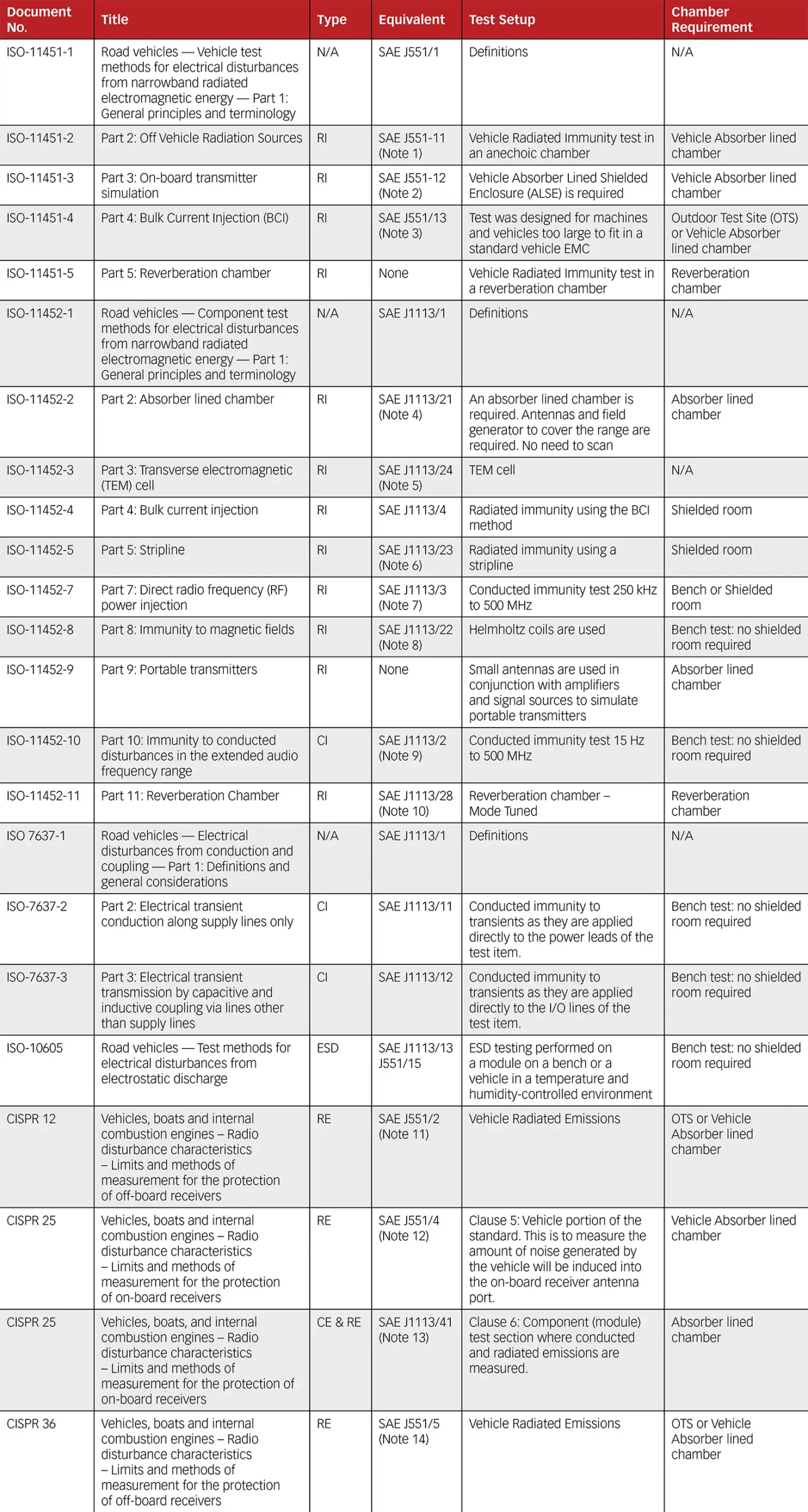
CISPR/D is responsible for developing and maintaining the standards used to measure the emissions produced by vehicles and their components. ISO/TC22/SC32/WG3 is responsible for developing and maintaining the standards used for immunity testing of vehicles and their components. ISO standards for the vehicle industry are mainly broken into two categories, vehicle (ISO 11451‑xx) or component (ISO 11452‑xx, ISO 7637‑xx). Table 1 on pages 128 and 129 provides an overview of the CISPR and ISO EMC standards for the automotive industry.
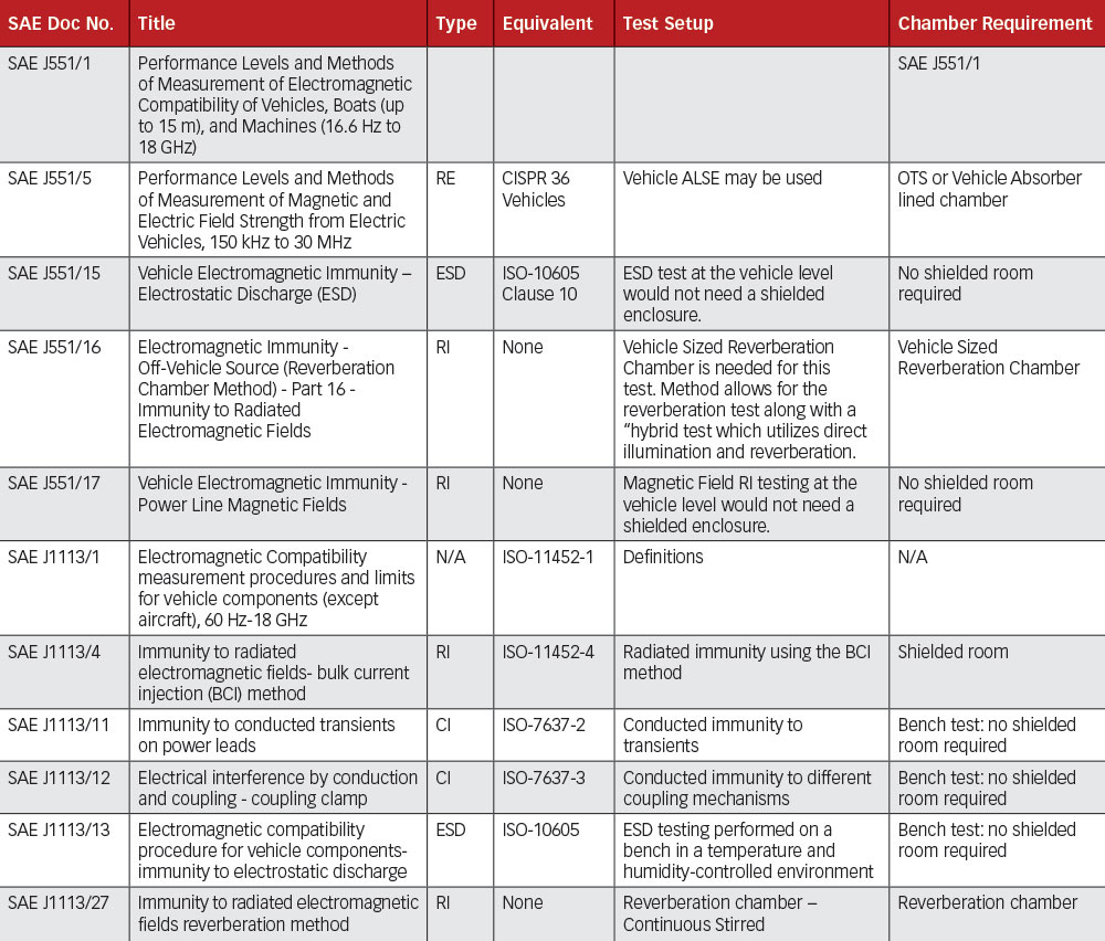
As with the ISO EMC standards, SAE EMC standards are mainly broken into two categories, vehicle (SAE J551‑xx) and component (SAE J1113‑xx). As can be seen in the notes of Table 1, many of the SAE standards are inactive because they have been withdrawn as complete standards and reserved for use to document differences from the international standards. Table 2 on page 130 does not show all the EMC standards related to automotive published by the SAE, but it gives an overview of the main standards and cross-references to the equivalent ISO or CISPR document. Table 2 shows the main SAE standards that are still active for both vehicle components and vehicles.
As with Table 1, Table 2 is not intended to show all the different parts of the standard, but to show the complexity of the standard documents and the many parts and methods that are covered under them. As mentioned above, government standards and directives in many cases refer to the CISPR or ISO methods. 2004/104/EC, which surpassed 95/54 EC, is a European directive for vehicle EMC. Its sections related to automotive components follow the directions given in the CISPR 25 document.
CISPR 12 radiated emissions measurements are made at either 3-meter or 10-meter test distances (although the limits are for the protection of off-board receivers at a distance ≥ 10 meters). The measurements are normally done on an outdoor test site (OTS) or in an absorber-lined shielded enclosure (ALSE) if the ALSE can be correlated to an OTS. Measurements for boats can also be made on the water. The correlation of the ALSE to an OTS has been a point of discussion over the past few years within the group of experts who are responsible for the maintenance of CISPR 12. The specification currently does not provide a method to achieve this correlation. A working group has been tasked with developing a method to validate an ALSE, OATS, or OTS that could be used for vehicle measurements. The plan is to add a site validation annex to CISPR 12 7th Edition when it is published.
At the present time J551‑11 is not used.
Note 2 SAE J551‑12 Withdrawn as a complete standard and reserved for use to document differences from ISO 11451‑3.
At the present time J551‑12 is not used.
Note 3 SAE J551‑13 Withdrawn as a complete standard and reserved for use to document differences from ISO 11451‑4.
At the present time J551‑13 is not used.
Note 4 SAE J1113‑21 Withdrawn as a complete standard and reserved for use to document differences from ISO 11452‑2.
At the present time J1113‑21 is not used.
Note 5 SAE J1113‑24 Withdrawn as a complete standard and reserved for use to document differences from ISO 11452‑3.
At the present time J1113‑24 is not used.
Note 6 SAE J1113‑23 This standard has been withdrawn.
Note 7 SAE J1113‑3 Withdrawn as a complete standard and reserved for use to document differences from ISO 11452‑7.
At the present time J1113‑3 is not used.
Note 8 SAE J1113‑22 Withdrawn as a complete standard and reserved for use to document differences from ISO 11452‑8.
At the present time J1113‑22 is not used.
Note 9 SAE J1113‑2 Withdrawn as a complete standard and reserved for use to document differences from ISO 11452‑10.
At the present time J1113‑2 is not used.
Note 10 SAE J1113‑28 Withdrawn as a complete standard and reserved for use to document differences from ISO 11452‑11.
At the present time J1113‑28 is not used.
Note 11 SAE J551‑2 Withdrawn as a complete standard and reserved for use to document differences from CISPR 12.
At the present time J551‑2 is not used.
Note 12 SAE J551‑4 Withdrawn as a complete standard and reserved for use to document differences from CISPR 25.
At the present time J551‑4 is not used.
Note 13 SAE J1113‑41 Withdrawn as a complete standard and reserved for use to document differences from CISPR 25.
At the present time J1113‑41 is not used.
Note 14 SAE J551‑5 Withdrawn as a complete standard and reserved for use to document differences from CISPR 36.
At the present time J551‑5 is not used.
Table 1: Some of the main CISPR and ISO EMC standards for the automotive industry
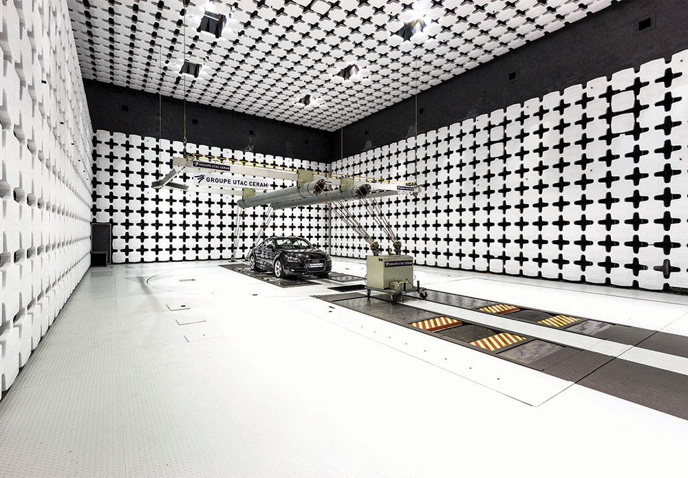
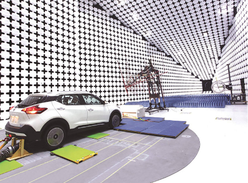
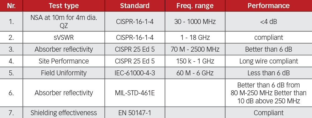
CISPR 25 has two parts. One part deals with a full vehicle or system test in which the antennas mounted on the vehicle are used to sense the noise generated by the different electric and electronic systems mounted on the same vehicle. This test shows how much noise generated by the vehicle will be introduced into the radio antenna port (sort of a self-immunity test). The other section of the standard deals with conducted and radiated measurements of vehicle components and modules. In this article, we are going to concentrate on the module radiated emissions test section of CISPR 25, and only briefly highlight some of the additions needed to support electric vehicles. More specifically, this article will concentrate on the chamber requirements for the standard.
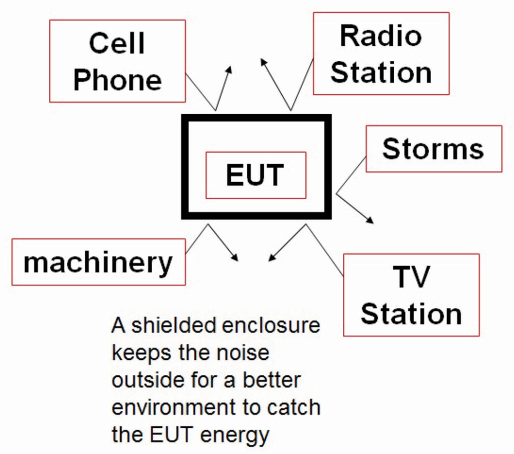
CISPR 25 states that the electromagnetic noise level in the test area has to be 6 dB lower than the lowest level being measured. Some of the radiated emissions limits found in CISPR 25 are as low as 18 dB (μV/m). This means that the ambient noise must be 12 dB (μV/m) maximum for a compliant environment. An RF-shielded room is typically used to keep RF signals from the external environment out of the test area so that the equipment under test (EUT) remains the dominant source of any radiated interference.
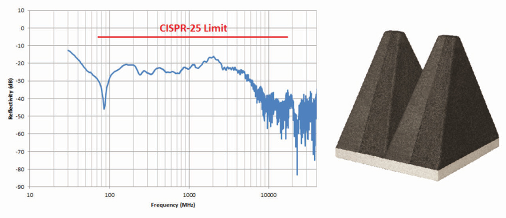
One of the most efficient and cost-effective is a polystyrene-based absorber that combines a high-performance ferrite tile with a polystyrene EMC absorber, having a 60cm x 60cm base and 60cm height. The main absorber substrate is based on expanded polystyrene (EPS), which is volumetrically loaded with lossy materials, and environmentally friendly fire retardants. Advanced uniform loading in the manufacturing process results in superior RF performance and excellent absorption uniformity. The closed cell structure of this type of absorber makes it suitable for use even in high-humidity environments. These features all contribute to providing a better controlled and predictable chamber test environment. Figure 3 presents the performance of one type of hybrid polystyrene absorber.
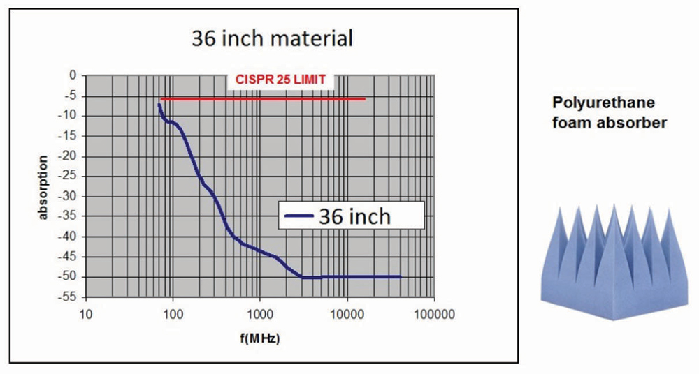
An alternative polyurethane absorber typically 36 inches (1m) in depth, EHP 36, can be used with improved high frequency performance due largely to the increased material length. But, without the benefit of the matching ferrite material used in the hybrid, the polyurethane only absorber suffers from reduced low frequency performance. Figure 4 shows the typical performance of this material and its compliance with the CISPR 25 limit.
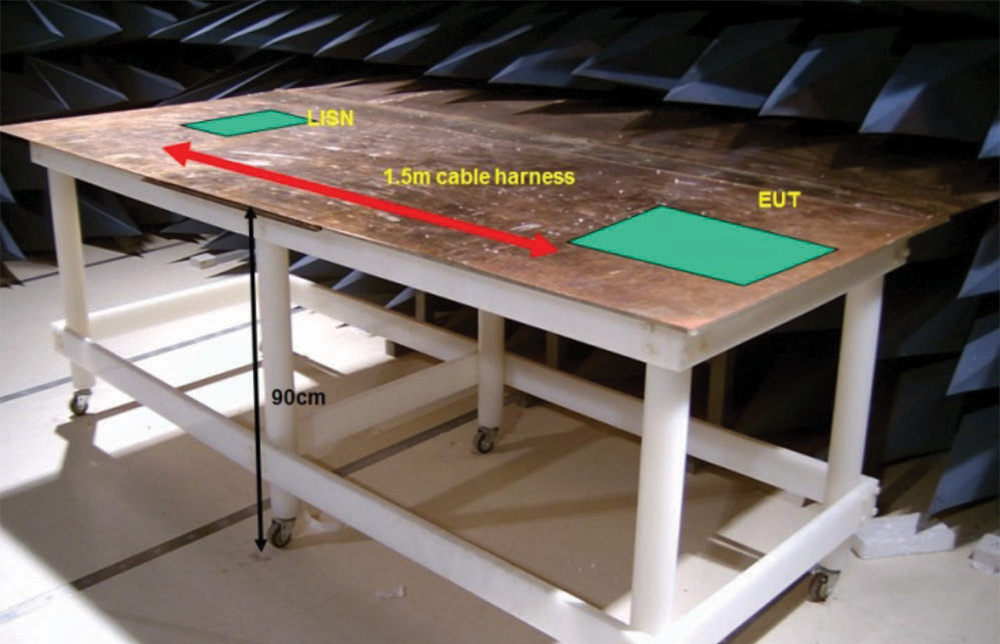
As Figure 5 shows, the bench must accommodate the largest EUT and all the cables that are needed to power and communicate with the device. The cables are routed in a cable harness that is positioned along the front edge of the bench. The cable harness itself is a significant component of the EUT and is the main component illuminated by the measurement antenna since at lower frequencies (frequencies for which the device under test is electrically small) the main coupling to radiated fields will occur through the cables feeding the device. This same procedure is used in MIL-STD 461 [3] and in ISO 11452 [4] and as shown in the illustration, a line impedance stabilization network is used to provide a defined impedance for the power to the device.
Figure 6 shows how the size of the bench is determined. The ground plane bench must extend all the way to the shield and in most cases, it is grounded to the wall of the shielded room. Grounding of the ground plane to the wall of the ALSE, especially if the chamber utilizes hybrid (ferrite/foam) absorbing material, has shown to reduce measurement system resonant conditions that may occur in the 10-70 MHz frequency range. The standard, however, does permit the bench to be grounded to the floor as an alternative.
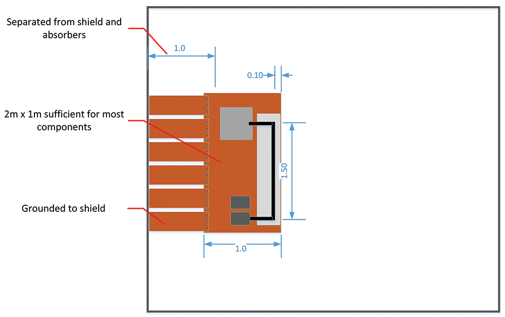
As defined in CISPR 25, the minimum width of the reference ground plane (bench) for radiated emissions shall be 1000 mm, the minimum length of the ground plane for radiated emissions shall be 2000 mm, or the length needed to support the entire EUT plus 200 mm, whichever is larger.
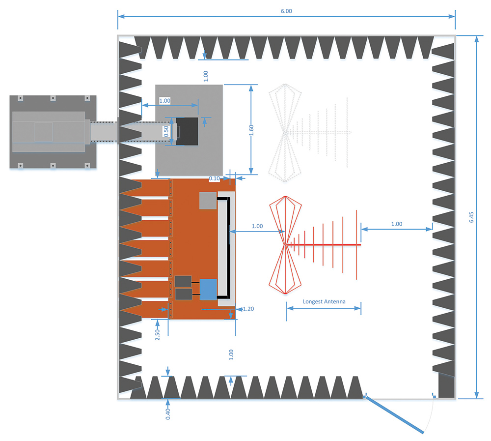
The minimum overall dimensions of the compliant chamber are determined by a series of dimensional relationships based primarily on the size of the test bench. With the use of a hybrid absorber with a depth of 60 cm to line the walls and ceiling of the chamber, Figure 7 shows that the width and length of the chamber is determined by the length of the absorber material with a one-meter space left between the bench (actually the DUT) and the tips of the absorbing material. For chambers that will also be used for e-motor testing, the motor is also part of the EUT. In some cases, the motor is supported on a separate structure adjacent to the test bench for mechanical reasons as shown in Figure 8. In this case, it still needs to be connected to the ground plane so in effect it will be an extension of the ground plane bench and subject to the minimum distances as defined in the standard.
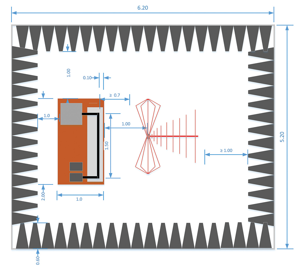
The other rule states that no part of the antenna can be closer than 1 m away from the tips of the absorbing material. These rules and recommended antennas define the length and height of the chamber. The 1 m distance to the cable harness is measured from the axis of the antenna elements for the monopole rod and the biconical antenna. For the log periodic dipole array (LPDA), the distance is measured from the tip of the antenna. Finally, for the horn antennas the distance is measured from the front face or aperture plane of the antenna. The longest antenna is usually the LPDA. A typical LPDA for the 200 MHz to 1 GHz range is about 1 m in overall length. In addition to the 1 m test distance and the 1 m for the antenna length, we have a 1 m clearance from the back of the antenna to the tips of the absorber. Figure 8 also shows the reference distances for an LPDA and bicon antennas in the chamber for the CISPR 25 setup.
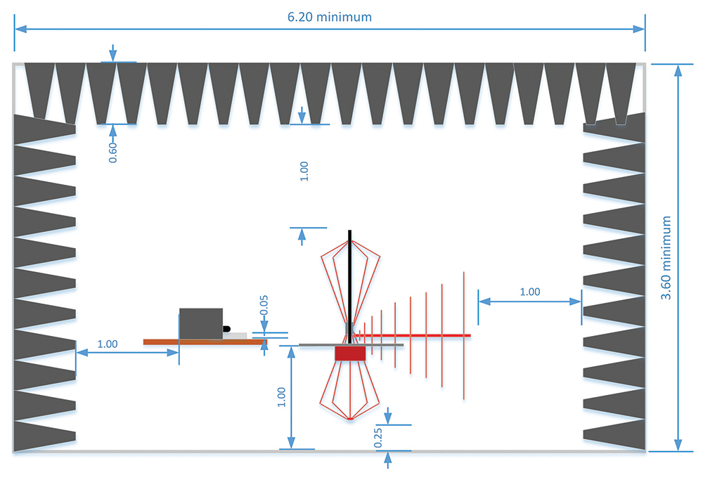
The height of the chamber will be driven by the longest antenna. The longest vertical antenna is usually the active rod monopole. The monopole is used with an extremely electrically small ground plane. Per the standard, the monopole rod is about 80 cm in length and it is positioned such that the ground plane is at the same level as the bench which as Figure 5 suggests is nominally 90 cm in height. The 1 m rule for the separation between the antenna and the absorber tip will again determine the minimum height of the chamber as shown in Figure 9.
With the components discussed in the previous sections, a chamber lined with 0.6m long hybrid absorber with a size of 5.2 meters wide by 6.2 meters long and 3.6 meters high will meet the minimum size requirements for performing compliant CISPR 25 tests. And, as we will see in the next section of this article, this chamber will also meet the requirements of ISO 11452‑2. Furthermore, since this is a shielded environment, most of the tests defined in standards requiring a shielded room can be performed inside the chamber described in the present section.
The CISPR 25 document prepared by the CISPR organization, and the requirements and guidelines on antennas and receivers, are already comprehensively defined in the CISPR 16-1-4 document [5]. The recommended antenna types used for the CISPR 25 measurements are therefore cross-referenced to the CISPR 16 document. For low frequencies, an active rod monopole antenna is preferred. At frequencies between 30 MHz and 200 MHz, a typical biconical antenna is the recommended antenna. From 200 MHz to 1 GHz, the antenna of choice is an LPDA and finally, from 1 to 5.95 GHz, the dual ridge horn (DRH) antenna can be a more compact and efficient antenna that easily meets the cross pole requirements of the standard, although lower gain LPDAs can still be used. It should be noted that bi log antennas are not allowed for CISPR 25 measurements and all references to the bi-log antenna have been removed from CISPR 25 5th Edition.
As mentioned at the beginning of the article, CISPR 25 also covers the measurement of emissions received by a vehicle antenna for a full vehicle setup. CISPR 25 5th Edition contains special setups to be used for the testing of electric vehicles (EVs) and hybrid electric vehicles (HEVs) and the modules (inverters, batteries, etc.) to be used on EVs and HEVs. The committee found that special testing and limits are required for the testing of these electric-driven vehicles and their components.
These vehicles represent a special case since there are high currents and voltages involved not only in normal operation but also during charging cycles. There will be more detailed information on the measurement setups to be used for EV and HEV measurements under different connection and charging scenarios. The testing adds new conditions for when the vehicle is not being driven, but connected to the mains or a charging station. This is currently already required as part of the European directive ECE Regulation 10, which outlines the EMC requirements for wheeled vehicles marketed in the European Union. Although ECE Reg 10 has its own limits for vehicle and ESA testing, it references both CISPR 25 and CISPR 12 for test setups and measurement techniques.
The ISO 11452-2 standard also requires that the tests be performed in an ALSE. As is common with most immunity measurements, the intent of the test is to produce RF field levels that can be disruptive or damaging to the EUT; the shielded room removes the risk of unintended disruption to other sensitive devices or equipment outside of the test region. In the US, as in most other countries, there are limits on the radiation of energy without licenses, at frequencies that could affect licensed broadcasts.
These tests are conducted at frequencies above 200 MHz and as discussed previously, the chance of resonant modes being developed inside the shield room is increased, so to reduce measurement errors the use of an absorber is required. The chamber is treated such that the reflectivity in the area of the EUT is -10 dB. Figures 3 and 4 show that for the 200 MHz to 18 GHz range, the -10 dB level is higher than the typical reflectivity of the recommended materials. This means that the same absorber used in the CISPR 25 chamber can be used in the ISO 11452‑2 chamber, with the relevant guidance on minimal separation distances between DUT, absorbers, and antennas. Antenna selection is in keeping with the need to generate the required field levels in the most effective and efficient manner given the cost of amplifiers. It is recommended that a dual ridge horn antenna be used for the 200 MHz to 2 GHz range. Above that, octave horns and standard gain horns with high gain are the preferred antenna choice.
Recently it has become important to understand the radiation characteristics of these antennas. The typical biconical antenna as shown in Figure 10 is an omnidirectional radiator. Its pattern shown in Figure 11 at 100 MHz is typical of the radiation pattern across the entire range. From these patterns, we can extract the half power beam width (HPBW). For the H plane, it is clear that the HPBW is larger than 180 degrees, and there is no main beam. For the E plane, the beamwidth ranges between 40 and 90 degrees. On the measured data, we can see the effects of the stem and balun holder on the pattern. The stem is oriented to the 180-degree mark. We can see how on the H plane the balun holder reduces the intensity of the radiation by 2 to 3 dB. The beamwidth of the measured data and the computed data track each other nicely.
Figure 12 shows a picture of an LPDA antenna and the numerical model created with specialized software. This is the other typical antenna type recommended by CISPR.
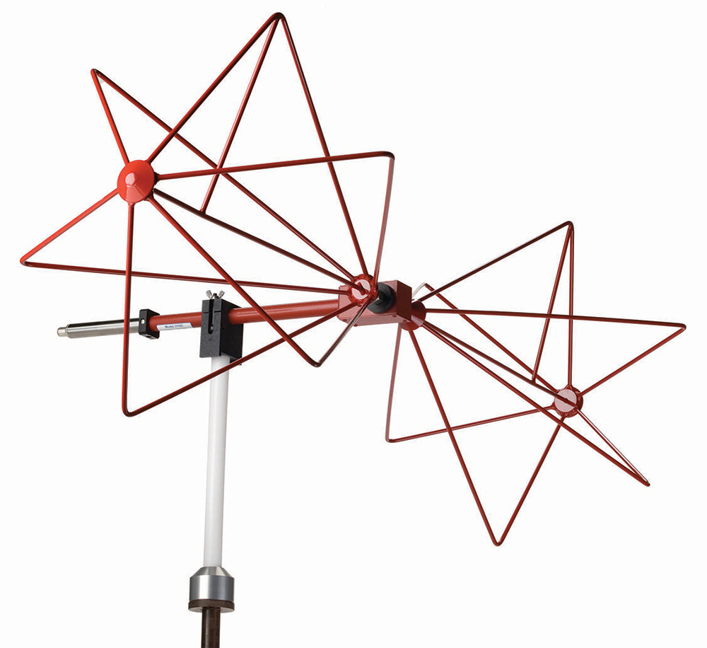
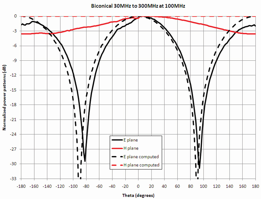
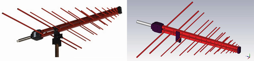
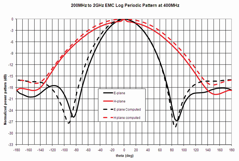
Figure 13 shows the data at 400 MHz, in which there is very good agreement between the measured and the computed results. The data for 1 GHz (shown in Figure 14) shows good agreement between measured and computed data for the main beam.
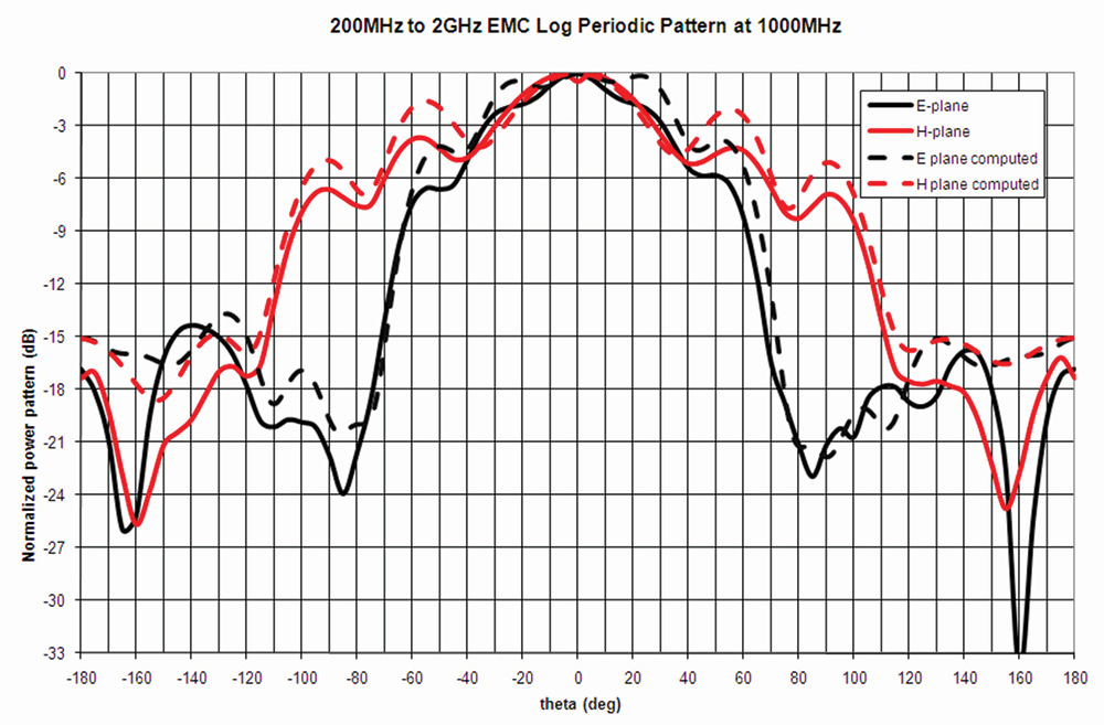
The HPBW of the LPDA antenna is usually fairly flat. This is especially the case for the center of the frequency band covered by the antenna. From about 200 to 1000 MHz, the antenna being measured exhibits an HPBW ranging from 100 to about 60 degrees for both planes.
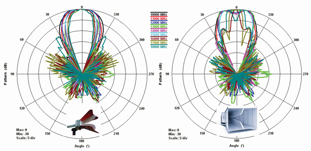
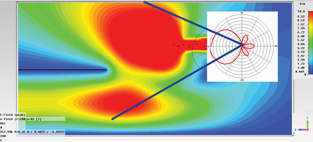
DRH antennas are the antenna of choice for higher frequencies. This family of antennas has been described numerous times in the literature. Their radiation pattern has been widely described. Reference [6] describes issues with the radiation pattern of these antennas at frequencies above 12 GHz for models operating in the 1 to 18 GHz range. References [7] and [8] introduce a new design for the 1 to 18 GHz range that has a better-behaved pattern where the main beam does not split into multiple beams. Figure 15 shows the measured radiation patterns for the horn analyzed in [6] and the one introduced in [7] and [8]. The data on the left shows a better-behaved pattern than the antenna on the right without the narrow beams and the split main lobe of the pattern.
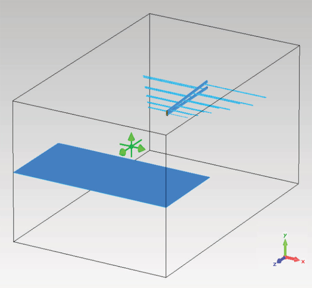
It is important to keep in mind that the data shown for the patterns is free space and far-field data. While it is true that it provides an idea of the antenna coverage, it can be misleading once we are in the presence of conductive benches. Figure 17 shows a typical setup for either CISPR 25 or ISO 11452-2. An antenna is placed 1 m away from the bench that is grounded.
For the horizontal polarization case, Figure 18 shows the dramatic effect that the bench has on the fields. While the cable harness will be covered by the antenna, the EUT will barely be in the illumination. This happens at all frequencies and it is related to the boundary conditions that are part of the electromagnetic phenomena.
This trend is continuing, and we have already started seeing the emergence of the next generation of immunity antennas.
The DRH antenna remains an attractive antenna for automotive EMC testing largely due to its wide operating bandwidth, stable radiating characteristics, and small size. However, the lower gain at its lower frequency end drives the need for high amplifier input power, making it impractical to achieve the required high field strength as required by ISO 11542-2 in some instances. In addition to achieving higher field levels for many immunity tests, it is also critical that the field uniformity (FU) requirements are satisfied (also required by ISO 11451-2). It is accepted that higher antenna gain is typically associated with narrower beam width which may lead to FU deterioration, so finding the correct compromise of size, gain, bandwidth, and beamwidth remains one of the antenna designer’s goals.
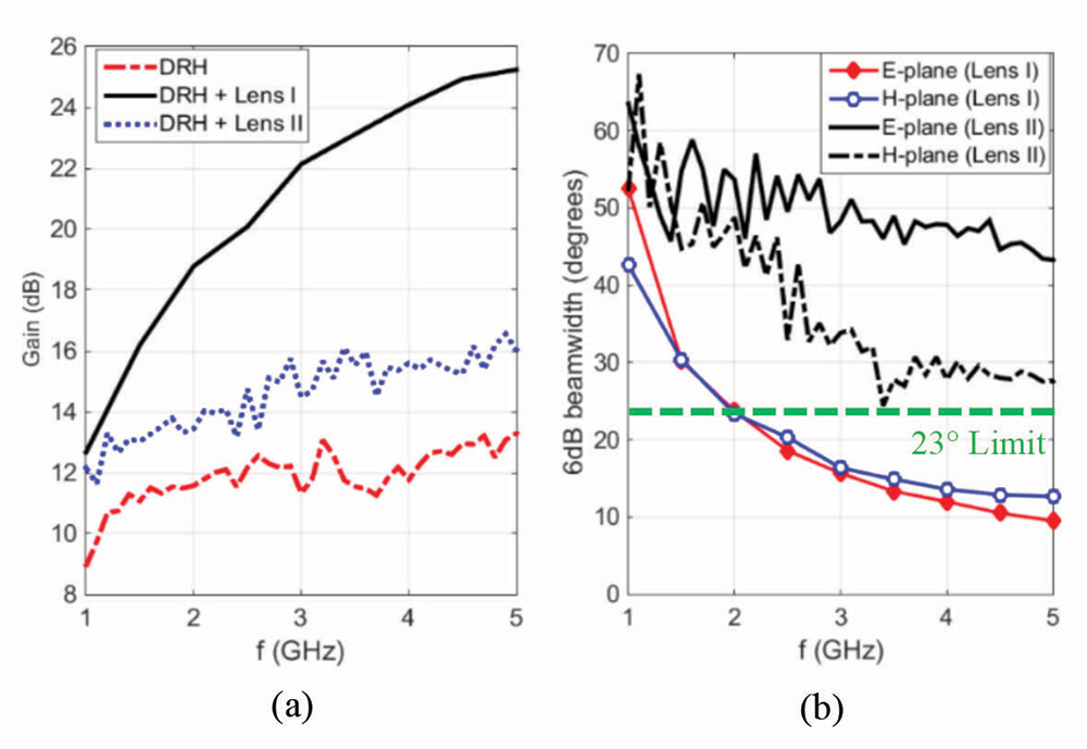
To solve this problem, horn antennas with lenses have become increasingly popular for automotive EMC testing applications. With dielectric lenses having properties such as low loss and wide operational frequency range, ridged horn antennas have been able to meet both field strength and FU requirements for automotive EMC testing in the 1 – 5 GHz frequency range. Figure 19 shows how adding a lens to a ridged horn antenna can drastically improve the gain vs bandwidth balance.
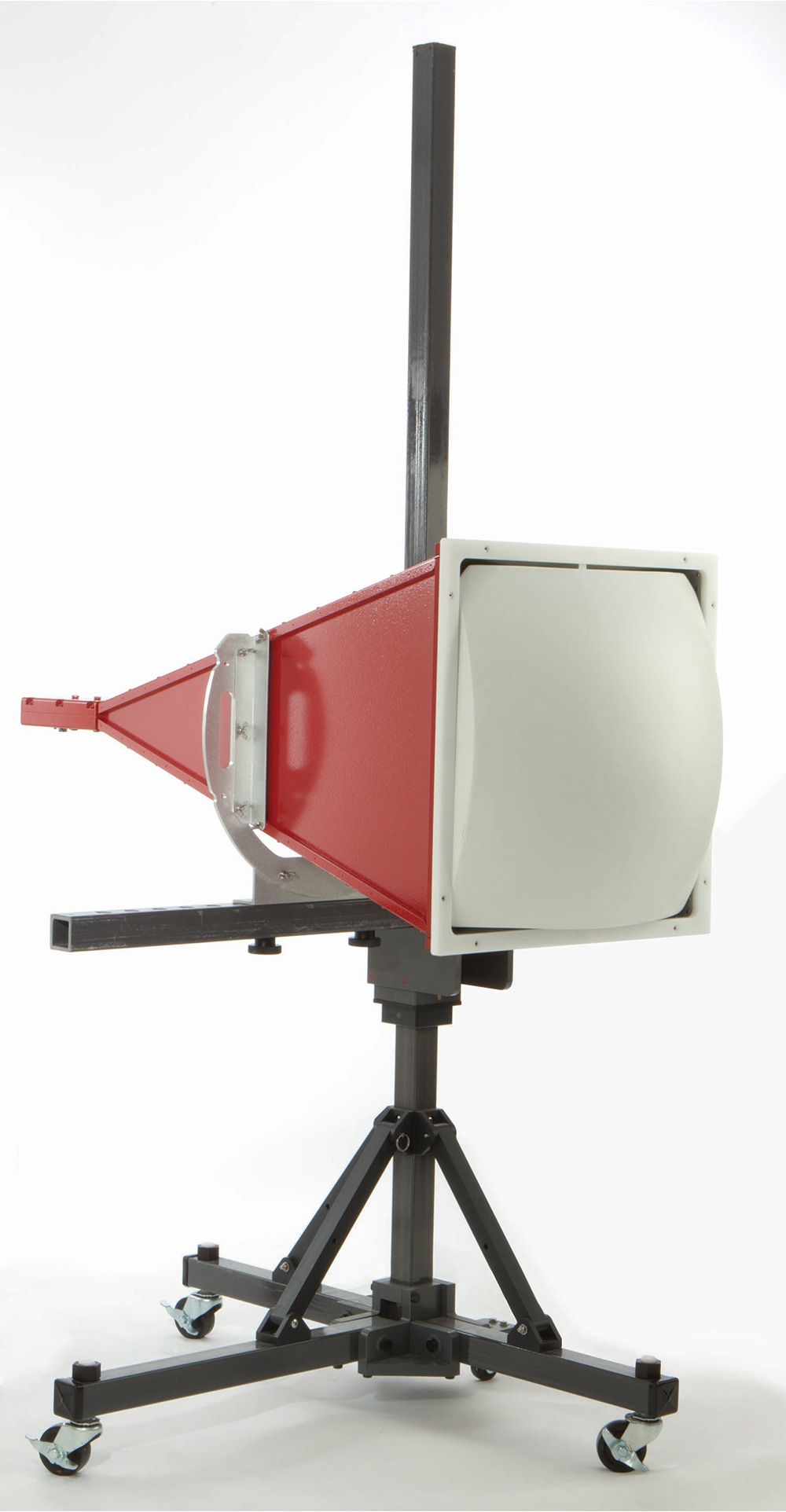
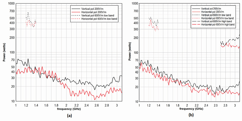
A ridged horn antenna with a lens (1-3.1GHz), mounted over a stand, is shown in Figure 20. Its lightweight meta-material lens increases the gain of the horn at a 1 m distance by 9 dBi. This characteristic makes the antenna ideal for automotive component immunity testing. Such high-gain antennas help to meet the narrow band high field strength requirement with less input power for automotive immunity testing. Figure 21 shows the power vs frequency plots required for this antenna to achieve 200V/m and 600V/m.
More recent chambers with a hybrid layout as the example shown in Figure 23 have been designed to also support antenna pattern measurements. In this example, the chamber has overall dimensions of 54m x 15m x 14m height including the 18m x 15m rectangular section. This chamber is also fully lined with the polystyrene absorber material providing optimum performance for EMC measurements with satisfactory performance for the low and intermediate frequency antenna pattern measurements. This chamber was designed to meet the CISPR 12/16/25, ISO 11451/11452, R10, SAE, and ANSI C63.4 standards.
In closing, the chamber installation example we’ve presented here highlights the notion that, wherever possible, new installations should take advantage of the best available technology and the latest revisions of the relevant standards, as is shown with the use of the proposed CISPR 25 5th Edition chamber validation method and, as in the case of a hybrid design, other tests and standards can be accommodated with careful absorber selection and treatment.
- CISPR 12, Vehicles, boats and internal combustion engines – Radio disturbance characteristics – Limits and methods of measurement for the protection of off-board receivers, Sixth Edition, IEC Geneva, Switzerland, 2007.
- CISPR 25, Radio disturbance characteristics for the protection of receivers used on board vehicles, boats, and on devices- Limits and methods of measurement, Fifth Edition, 2021.
- MIL-STD 461, Requirements for the control of Electromagnetic Interference Characteristics of Subsystems and Equipment, Department of Defense Interface Standard 10, December 2007.
- ISO 11452, Road vehicles – Component test methods for electrical disturbances from narrowband radiated electromagnetic energy – Part 2: Absorber-lined shielded enclosure, Second Edition.
- CISPR 16-1-4, Specification for radio disturbance and immunity measurement apparatus and methods, Part 1-4: Radio disturbance and immunity measuring apparatus – Antennas and test sites for radiated disturbance measurements, Third Edition, IEC Geneva, Switzerland, 2010.
- C. Bruns, P. Leuchtmann, and R. Vahldieck “Analysis of a 1-18 GHz Broadband Double-Ridge Antenna,” IEEE Transactions of Electromagnetic Compatibility, Vol 45, No. 1, pp.55-60, February 2003.
- V. Rodriguez “New Broadband EMC Double-ridge Guide Horn Antenna,” RF Design, May 2004, pp. 44-50.
- V. Rodriguez, “A New Broadband Double Ridge Guide Horn with Improved Radiation Pattern for Electromagnetic Compatibility Testing,” 16th International Zurich Symposium on Electromagnetic Compatibility, Zurich, Switzerland, February 2005.
- V. Rodriguez, “Improvements to Broadband Dual Ridge Waveguide Horn Antennas,” 2009 IEEE International Symposium on Antennas and Propagation and USNC/URSI National Radio Science Meeting, Charleston, SC, June 1-5, 2009.
- V. Rodriguez, “Recent Improvements to Dual Ridge Horn Antennas: The 200 MHz to 2 GHz and 18 GHz to 40 GHz Models,” 2009 IEEE International Symposium on EMC, Austin, TX, Aug 17-21, 2009.
- CISPR 36, Electric and Hybrid Electric Road Vehicles – Radio disturbance characteristics – Limits and methods of measurement for the protection of off-board receivers below 30 MHz, First Edition, IEC Geneva, Switzerland 2020.