n Part 1 of this article, we showed that the trend of progressively migrating both ESD and EMC immunity from the system/board level to the component level is creating unprecedented challenges for the component ESD designer. We reviewed the implications of EMC-ESD Immunity co‑design, along with several case studies.
With the unavoidable re-purposing of the system-level standards to validate component-level robustness (IEC 61000-4-2 [1], ISO 10605 [2]), several gaps at the standards level place ESD engineers in the awkward position of creating their own standards. Even worse, the practice of reporting system-level performance in components datasheets is completely dependent on each ESD engineer’s interpretation of the standards, hence making those specs of questionable value.
Part 2 of this article focuses on the specific ESD design challenges stemming from the fact that all relevant system-level standards were created to validate systems and not components.
To rigorously assess the impact of the setup differences detailed in the previously mentioned standards, we offer the circuit analog shown in Figure 1. Each major component of the testing setup is included as a circuit element and the impact of those elements allowed variation to the entire circuit performance that can then be assessed. The specific components of the analog are the ESD generator (or, colloquially, ESD gun), the impedance coupling between the ESD gun and the target/DUT, the target/DUT, and the ground return path between the ESD gun and the target/DUT.
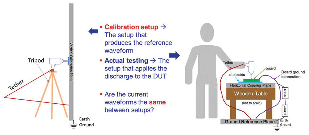
- Calibration method/set-up does not allow a “hand‑held” gun; the gun must be mounted (“tripod or equivalent non-metal low loss support” [1]). Unfortunately, the gun is made to be “hand‑held” and it is commonly used in this way.
- There are numerous reports of operator dependent variations, which are not included in the standard, and impact the calibration waveform [3]. We have experienced first-hand not only significant IEC level differences between guns from different manufacturers, but also from different gun models from the same manufacturer.
- In general, the impact of gun positioning and operator to gun coupling cannot be ignored.
The ESD gun can now be held by a human operator and the position and shape of the tether is much less stringently controlled. One should not assume that the current waveform introduced to a device under test (DUT) is exactly the same as the waveform produced in the calibration setup. In fact, significant deviations in the current waveform can result, leading to unexpected performance (both pass and fail) and unrepeatable results.
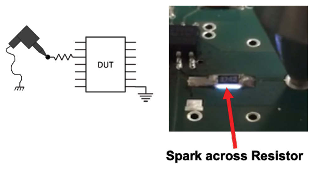
While the coupling between the ESD gun and the target/DUT (Zseries in Figure 1) may seem like an insignificant contributor to the overall performance of the circuit, remember that an ESD gun in direct contact with the target/DUT is not the only configuration—in fact, the coupling between the ESD gun and the target/DUT can be quite different for some configurations. Many automotive system-level test standards [4‑7] apply discharge through a variety of gun-target couplings. In addition to the most common gun-target coupling (i.e., contact discharge), there are four other couplings (some used in conjunction), namely:
- Spark: air discharge
- Wiring harness/cable
- Common-mode choke
- Series resistor
This becomes an extremely important factor in J2962-x automotive standards [4, 5], in which air-discharges are applied directly to the BUS signal wires in the wiring harness. But current waveforms are not generally monitored in-situ during system-level testing; the person applying the discharge has no reasonable gauge of the severity of the current pulse that was actually delivered.
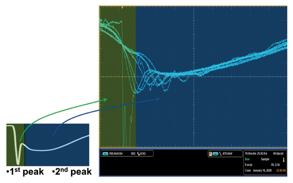
The current waveform shown in the IEC 61000-4-2 standard consists of a fast-rise time to a peak current, followed by a drop in current and a slower rise-time to a second peak. Figure 4 shows an expectation of two clearly distinguishable peaks (for a negative discharge) in the lower left corner. This expected waveform has a green region (indicating the 1st peak region) and a blue region (indicating the 2nd peak region). To the right of Figure 4, actual measured current waveforms are shown. These waveforms were all generated in the same test setup, by the same operator, at the same voltage level. The only variances were the speed and angle at which the operator approached the target with the ESD gun.
Another factor in air-discharge testing is the challenge of holding the pre-charge voltage on the ESD gun before spark formation. In cases where the target is a very sharp geometry (such as a wire) it is quite possible to lose charge through corona discharge. While the ESD gun may have been programmed to deliver a 10-kV discharge, at the time of spark formation perhaps only a 5-kV equivalent charge remains. In fact, doubling the discharge voltage in this case may lead to no increase in discharge current whatsoever.
So what does it mean to apply a 10-kV air-discharge to a DUT and observe no failure? Is the DUT robust or was a “soft” current waveform delivered? If a DUT fails 10-kV, does this mean it will be weak in a different test environment (or in the actual application)? Given the lack of fidelity between the programmed discharge voltage and the actual current-waveform delivered, no meaningful conclusions can be reached about the robustness of a DUT by a simple statement that the DUT passed or failed discharge voltage-level testing.
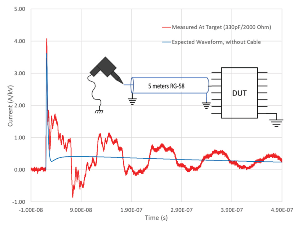
Figure 5 shows an example of an ESD discharge applied through 5 meters of RG-58 cable, relative to the expected waveform without a cable present. If the significant reflections demonstrated in Figure 5 are not anticipated during the DUT design phase, unexpected failures can result.
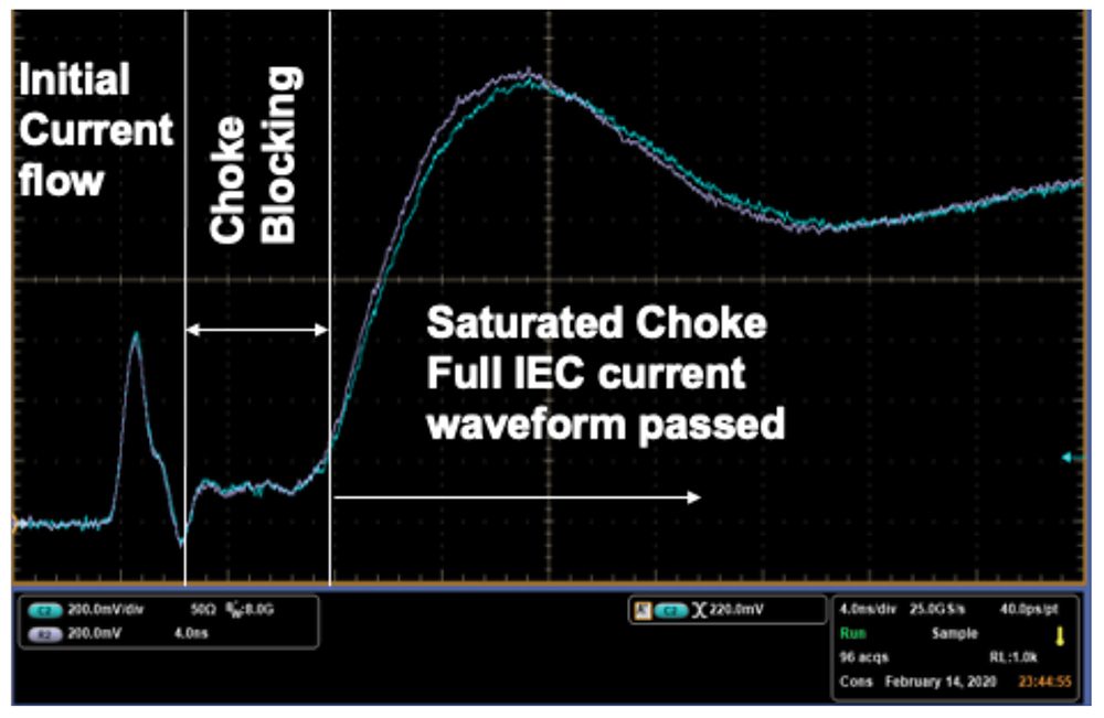
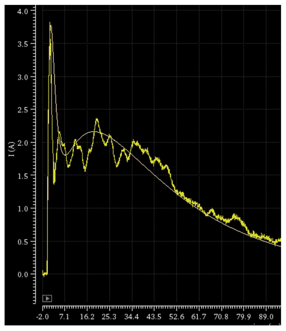
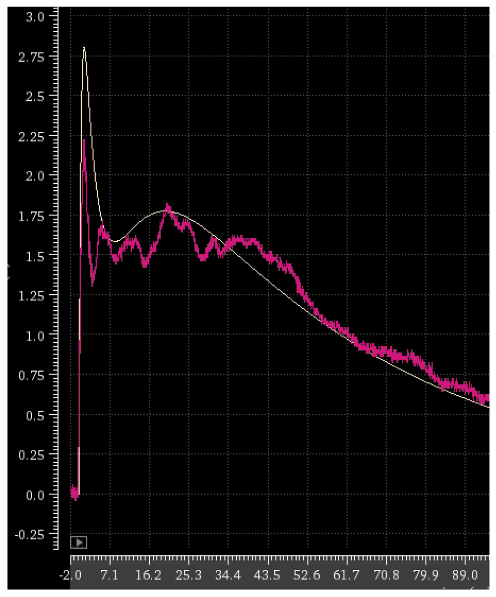
Unfortunately, a CMC can display a strong saturation behavior (due to the ferrite saturation [10‑12]), which results in a drastic reduction of the inductance over a certain threshold current. In addition, a CMC features an undesirable snapback characteristic for ESD current densities. This highly non-linear behavior can force the component-level ESD protection in and out of snapback multiple times, depending on the current density. Figure 6 shows the typical non-linear waveform of a CMC in response to a full IEC event.
The choke allows initial current flow, due to displacement current of the quasi-differential signal. This is followed by a “blocking” period, corresponding to the common mode signal. Eventually, the choke saturates, causing low impedance, and therefore high current flow.
This complex waveform depends on several parameters, including:
- Discharge level;
- Board parasitics; and
- Unspecified/uncharacterized choke parameters (i.e., two nominally identical CMCs will yield completely different IEC results).
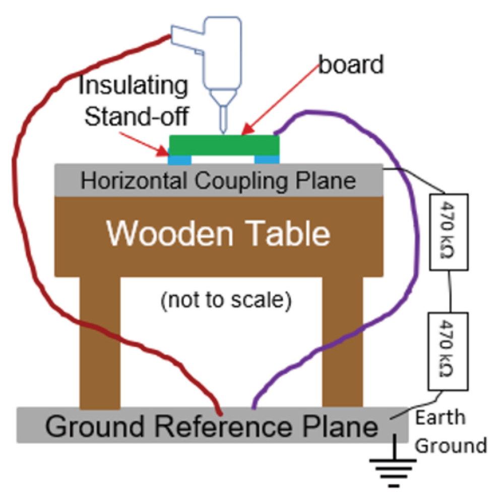
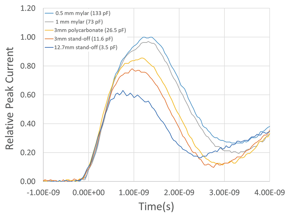
- Board to horizontal coupling plane (HCP) capacitance inserted in the high-frequency path, and
- Added wire impedance in the low-frequency path.
This article focuses on the specific ESD design challenges stemming from the fact that all relevant system-level standards were created to validate systems and not components.
- Metal fixture between board and HCP, tether directly to grounded HCP, and
- Strong low-impedance bond between board and HCP.
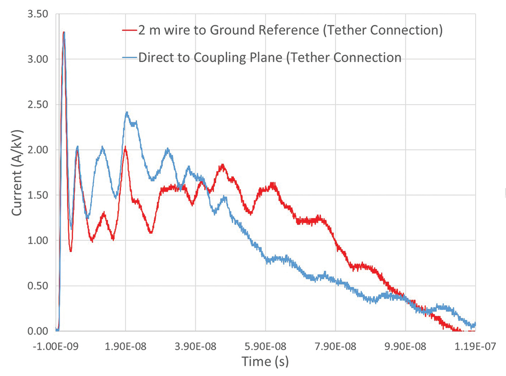
If we look at the low frequency return path, it is mainly driven by the gun tether. Inserting a wire between the board and the ground reference plane adds impedance in the low frequency return path (Figure 10).
As shown, the test-setup with respect to the ground return path can have significant impact on the shape and severity of the current waveform delivered to the DUT. Seemingly subtle changes in the test-setup can lead to consequential changes in testing results, leading to repeatability issues. Similarly, seemingly subtle differences between different test-setups can lead to differing testing results between two test facilities, leading to reproducibility issues.
However, the agreement is not good for a 100 Ohm load (Figure 12), which begs the question of whether the gun or the model is more correct. Because the standards do not set an expectation, the question cannot be answered.
- IEC 61000- 4-2, “Electromagnetic compatibility (EMC), Part 4-2: Testing and measurement techniques – Electrostatic discharge immunity test”
- ISO 10605, “Road vehicles – Test methods for electrical disturbances from ESD”
- M. Dekker, T. Smedes, G. Notermans and R. Ashton, “HMM Failure Level Variations Revisited,” 2019 41st Annual EOS/ESD Symposium (EOS/ESD), Riverside, CA, USA, 2019, pp. 1-8, doi: 10.23919/EOS/ESD.2019.8870002.
- J2962-1, “Communication Transceivers Qualification Requirements—LIN.”
- J2962-2, “Communication Transceivers Qualification Requirements—CAN.”
- IEC 62228-1, “Integrated circuits – EMC evaluation of transceivers – Part 1: General conditions and definitions,” 2018.
- IEC 62228-2, “EMC evaluation of transceivers – Part 2: LIN transceivers,” 2016.
- IEC 62228-3, “Integrated circuits – EMC evaluation of transceivers – Part 3: CAN transceivers,” 2019.
- S. Bub, M. Mergens, A. Hardock, S. Holland and A. Hilbrink, “Automotive High-Speed Interfaces: Future Challenges for System-level HV-ESD Protection and First- Time-Right Design,” 2021 43rd Annual EOS/ESD Symposium (EOS/ESD), Tucson, AZ, USA, 2021, pp. 1-10, doi: 10.23919/EOS/ESD52038.2021.9574746.
- S. Frei, M. Senghaas, R. Jobava, and W. Kalkner, “The influence of speed of approach and humidity on the intensity of ESD,” in Proc. 13th Int. Zurich Symp. EMC, Zurich, Switzerland, Feb. 1999, pp. 105–110.
- M. Ammer, S. Miropolskiy, A. Rupp, F. z. Nieden, M. Sauter and L. Maurer, “Characterizing and Modelling Common Mode Inductors at High Current Levels for System ESD Simulations,” 2019 41st Annual EOS/ESD Symposium (EOS/ESD), Riverside, CA, USA, 2019, pp. 1-7, doi: 10.23919/EOS/ESD.2019.8870005.
- N. K. Kranthi, J. di Sarro, R. Sankaralingam, G. Boselli and M. Shrivastava, “Insights into the System-Level IEC ESD Failure in High Voltage DeNMOS-SCR for Automotive Applications,” 2020 42nd Annual EOS/ESD Symposium (EOS/ESD), Reno, NV, USA, 2020, pp. 1-7.