n [1], we discussed the impact of decoupling capacitors and a PCB trace length on the signal integrity in a CMOS inverter circuit. In this article, we evaluate the impact of the capacitors and trace length on radiated emissions. It is shown that the radiated emissions from the PCB with short traces are lower than those with long traces. It is also shown that the decoupling capacitors have little impact in the monopole antenna range, a significant positive impact in the bicon antenna range, and a negative impact in the log-periodic antenna range.
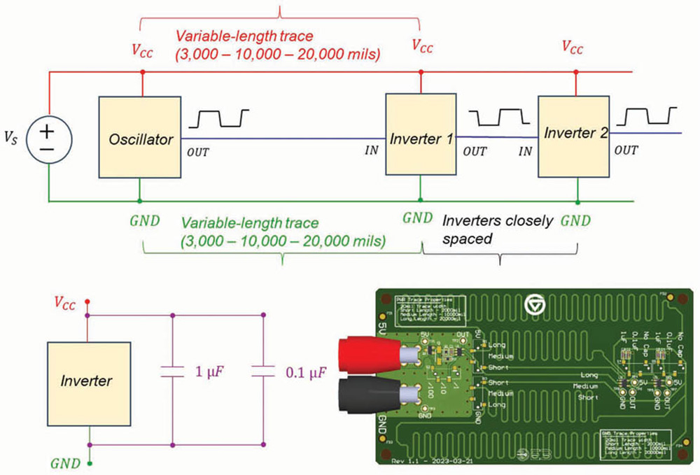
In this study, trace length is varied between 3,000 mils (short trace) and 20,000 mils (long trace). Additionally, the PCB is tested in two configurations: without the decoupling capacitors and with decoupling capacitors by each inverter (0.1 µF and 1 µF).
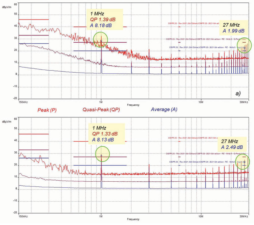
Case 3A: Short trace vs. long trace – Monopole antenna
Radiated emission results are shown in Figure 2.
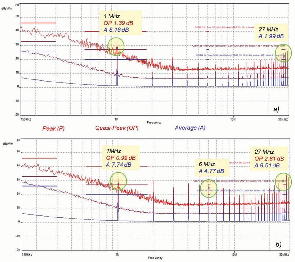
Both traces showed similar failures at 1 MHz. Long trace failed average detector at 6 MHz. At 27 MHz, the short trace failed average detector while the long trace failed quasi-peak and average detector. The average detector failure for the long trace was about 7.5 dB higher than that for the short trace. Overall, the short trace outperformed the long trace.
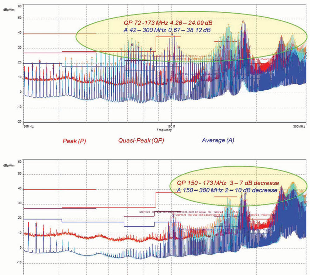
Case 3B: Short trace vs. long trace – Bicon antenna
Radiated emission results for both traces are shown in Figure 3.
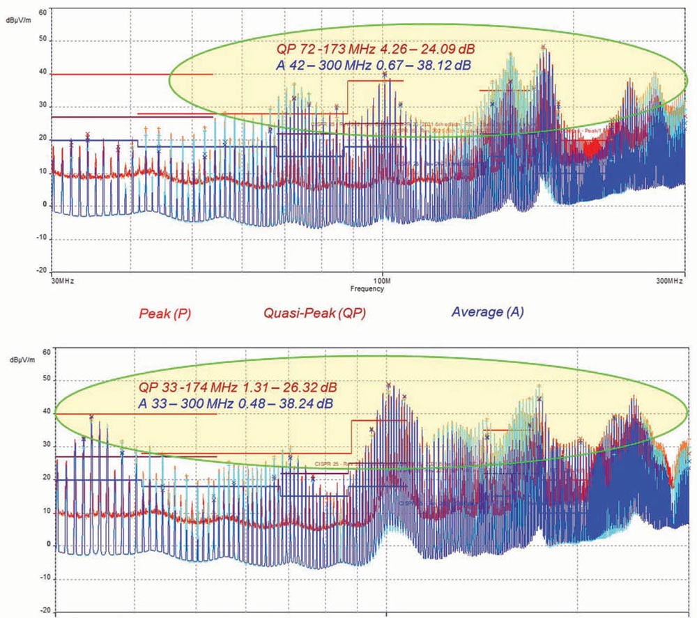
Both traces showed multiple failures. The short trace failed quasi-peak detector in the frequency range 72 – 173 MHz by the margin 4.26 – 24.09 dB. It failed average detector in the frequency range 42 – 300 MHz by the margin 0.67 – 38.12 dB.
The long trace failed quasi-peak detector in the frequency range 33 – 174 MHz by the margin 1.31 – 26.32 dB. It failed average detector at every frequency in the range 33 – 300 MHz by the margin 0.48 – 38.24 dB.
Overall, the long trace showed more failures over a wider frequency range.
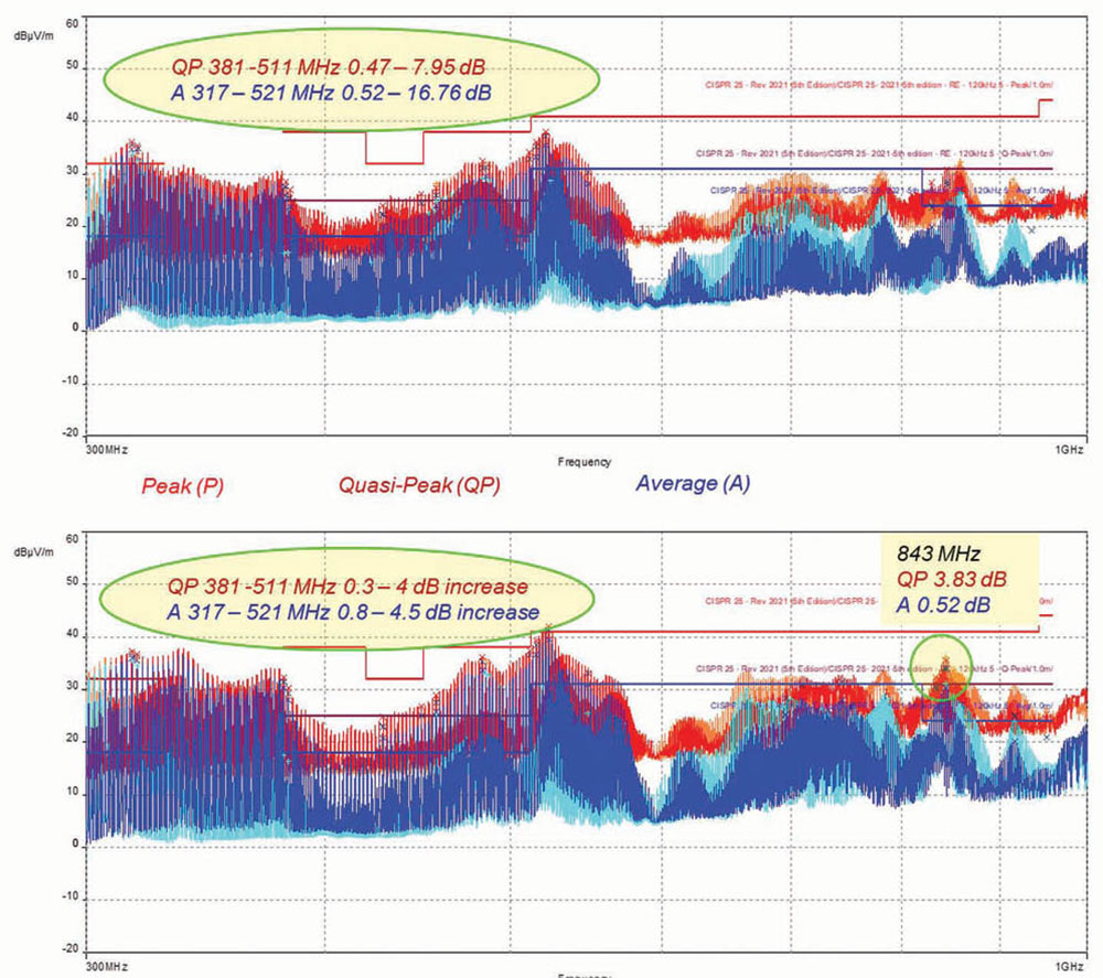
Case 3C: Short trace vs. long trace – Log-periodic antenna
Radiated emission results for both traces are shown in Figure 4.
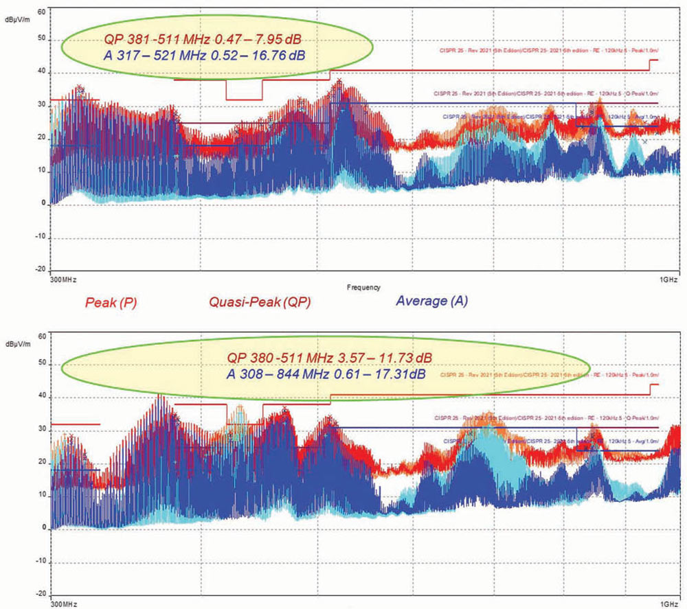
Both traces showed quasi-peak detector failures in the similar frequency range of 380 – 511 MHz, with the long trace exceeding the limits by a higher margin. The short trace showed average detector failures in the frequency range of 317 – 521 MHz, while the long trace showed failures in the frequency range of 308 – 844 MHz. Overall, the long trace showed more failures over a wider frequency range.
Case 4A: Short trace with and without decoupling capacitors – Monopole antenna
Radiated emission results for both traces are shown in Figure 5 on page 28.
The decoupling capacitors had a negligible impact at the frequencies where the failures occurred.
Case 4B: Short trace with and without decoupling capacitors – Bicon antenna
Radiated emission results for both traces are shown in Figure 6.
Quasi-peak detector: Capacitors eliminated failures in the frequency range 72 – 150 MHz. In the frequency range 150 – 173 MHz, many failures were eliminated, and the remaining ones decreased by 3 – 7 dB.
Average detector: Capacitors eliminated failures in the frequency range 42 – 100 MHz. In the frequency range 150 – 300 MHz, multiple failures were eliminated, and the remaining ones decreased by 2 – 10 dB.
Overall, the capacitors had a significant positive impact on radiated emissions.
Case 4C: Short trace with and without decoupling capacitors – Log-periodic antenna
Radiated emission results for both traces are shown in Figure 7.
Quasi-peak detector: Capacitors did not eliminate or reduce the failures in the frequency range 380 – 511MHz. They increased the failures by 0.3 – 4 dB. Additionally, the capacitors created a new failure at 843 MHz.
Average detector: Capacitors did not eliminate or reduce the failures in the frequency range 317 – 521MHz. They increased the failures by 0.8 – 4.5 dB. Additionally, the capacitors created new failures at 843 MHz.
Overall, the capacitors had a negative impact on radiated emissions.
Case 5A: Long trace with and without decoupling capacitors – Monopole antenna
Radiated emission results for both traces are shown in Figure 8.
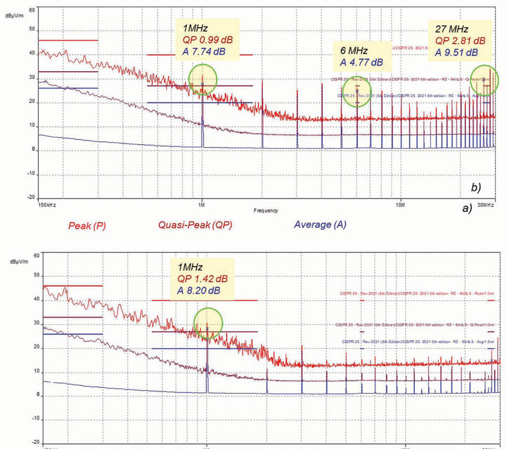
The decoupling capacitors had minimal impact at 1 MHz. However, they eliminated failures at 6 MHz and 27 MHz.
Case 5B: Long trace with and without decoupling capacitors – Bicon antenna
Radiated emission results for both traces are shown in Figure 9.
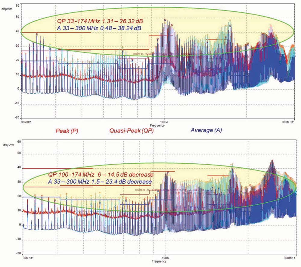
Quasi-peak detector: Capacitors eliminated failures in the frequency range 33 – 100 MHz. In the frequency range 100 – 174 MHz, several failures were eliminated, and the remaining ones decreased by 6 – 14.5 dB.
Average detector: Capacitors eliminated several failures in the frequency range 33 – 65 MHz. The remaining failures over the entire frequency region were either eliminated or decreased by 1.5 – 23.4 dB.
Overall, the capacitors had a significant positive impact on radiated emissions.
Case 5C: Long trace with and without decoupling capacitors – Log-periodic antenna
Radiated emission results for both traces are shown in Figure 10.
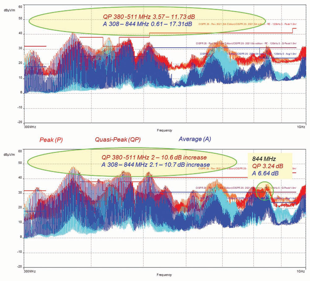
Quasi-peak detector: Capacitors increased the failures in the frequency range 380 – 511 MHz by 2 – 10.6 dB. They introduced a new failure at 844 MHz.
Average detector: Capacitors increased the failures in the frequency range 319 – 511 MHz by 2.1 – 10.7 dB. They introduced a new failure at 844 MHz.
Overall, the capacitors had a negative impact on radiated emissions.
- Bogdan Adamczyk and Mathew Yerian-French, “Impact of a Decoupling Capacitor and Trace Length on Signal Integrity in a CMOS Inverter Circuit,” In Compliance Magazine, January 2024.