Part 1: Overview

have always wanted to write articles on filter design. Needless to say, the subject alone can easily spawn a book. This is because, in the world of electronics, we have power filters, transformers, low-frequency filters, digital circuit filters, and analog circuit filters. Each design requires its unique and dedicated filter design principles. Additionally, we have different requirements, and it is fair to say that most commercially available filters are designed to meet certain EMC specifications. Hence, they are most likely designed to work efficiently with the test setup, particularly the line impedance stabilization network (LISN) for conducted emission tests.
Given the numerous points to consider, capturing everything in one article is nearly impossible. My favorite books and articles on this subject are listed in the reference section [1]-[3], and I encourage readers to explore them.
This series of articles focuses primarily on power filters for switched-mode power converters and similar applications. By defining this boundary, I am concentrating on conducted emissions (from 9 kHz to 110 MHz) and radiated emissions (from 30 MHz to 1 GHz). Although most power supplies also need to meet transient protection requirements, we will not cover transient protectors in this series. Topics related to harmonics, as well as digital and analog circuit filter design, are beyond the scope of this series. When referring to switched power converters and similar applications, I mean power converters such as AC‑DC, DC‑DC, DC-AC, and motor drive applications.
We want to discuss filter design in this specific field because we now live in an era where we aim to electrify everything for the good purpose of making a more sustainable future. In this article, which is Part 1 of the series, I will provide an overview of the filter design principles for switched conversion applications.
Most of my work involves helping clients meet these EMC requirements, whether they are the stringent military specifications or the relatively easier industrial emission standards. However, engineers sometimes face unique challenges. For example, a client in the semiconductor manufacturing industry required an extremely EM-quiet environment for their machines to operate accurately. This meant they needed to control the electromagnetic interference (EMI) based on their own system requirements. In this scenario, there is no LISN per se, as the power supply design depends solely on their specific system. Consequently, the system’s impedance is unlikely to match a 5 or 50 µH LISN [5].
Although the requirements differ, they all aim to achieve one end goal: operating the product with controlled EM noise to avoid interfering with other equipment and preventing nuisance issues within the product/system itself.
I highlight this because I experienced it first-hand. During my PhD research on sophisticated switching schemes, I lacked EM knowledge. It was only years later, after understanding EM theory, that I could view the problem from a different perspective. Many EMC engineers likely have similar stories.
It’s unrealistic to expect EMC engineers to possess the same level of knowledge of power converters as power electronics design engineers. EMC engineers have their own disciplines, including testing skills and simulations. However, a basic understanding of power converter fundamentals is always useful.
In my view, the two essential circuits that engineers need to understand are the buck converter and the flyback converter. Why? The buck converter represents the most basic DC-DC step-down converter, widely used in power conversions. Understanding the buck converter helps in understanding other applications, such as boost converters, which are essentially the mirror image of buck converters (as shown in Figure 2 (a) vs (b)).

As shown in Figure 2, most motor drive applications, whether DC brushed motors or brushless DC motors (single-phase or three-phase), are essentially made of buck converters. For instance, three-phase brushless DC motors use hardware that is essentially three synchronous buck converters, regardless of the control method (sinusoidal pulse width modulation (PWM), space vector modulation (SVM), field orientated control (FOC), etc.). Similarly, the concepts of hot loop and switch nodes in the buck converter apply to motor drive applications. The hot loop areas and the switch nodes are highlighted in Figure 2. The hot loop area is defined as the loop area where the worst di/dt current circulates, indicating a high level of magnetic field (near field). This highlights the importance of reducing this area. The switch node is defined as the worst dv/dt voltage node in the circuit, indicating a high level of changing electric field. This underscores the importance of minimizing capacitance coupling nearby.
Understanding flyback converters helps in understanding other circuits like forward converters. Flyback converters are popular in the power range under 150W. When power requirements increase, we often see topologies such as phase-shift full bridge (PSFB), dual-active-bridge (DAB), LLC, etc. However, the principles of these higher power converters are not far from those of a flyback converter.
Isolated flyback converters are more complex due to their requirement for a transformer. It is worth noting that, unlike the ideal transformer, current does not flow simultaneously in both windings of the flyback transformer but rather functions as an inductor with two windings; a more descriptive name should be “two winding inductor” [6]. In most applications, since the flyback transformer stores energy, an air gap is needed. During power conversion, energy moves from the input bulk capacitor to the transformer’s air gap and then to the output capacitor.
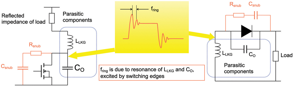
The presence of the transformer introduces additional considerations. From an EMC perspective, the first is leakage inductance. The leakage inductance of the transformer forms an L-C resonance circuit with the parasitic capacitance of the switching device, causing overshoot and ringing. This is why a snubber circuit is often needed for the converter. This is illustrated in Figure 3.
Both buck and flyback converters generate broadband noise, which is often a significant noise culprit in electronic systems. The concept and consequence of broadband noise is well explained in [7]. In terms of noise profiles, the two circuits discussed above are very similar.
- Understand your circuit’s noise profile: This can be achieved through benchtop tests and/or SPICE simulations.
- Determine the required dB reduction (attenuation): Based on the results, identify how much attenuation is needed across the frequency range.
- Select the L, C, and R components: Choose components to meet the required reduction, often determined by the filter’s cut-off frequency.
- Perform a simulation: Verify that the noise is reduced (e.g., by 60 dB) through simulation.
- Implement the filter: Build the filter based on your design.
- Measure the performance: Test the filter and observe the results. Often, the actual performance may not match your expectations.

We will discuss this in greater detail later, but at a top level, here are common areas that engineers often overlook:
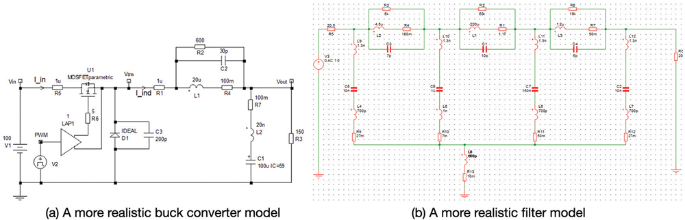
- Simulation model detail: Does the model capture all parasitics, such as leakage inductance of transformers and parasitic capacitance of switching devices (Figure 5(a))?
- Inclusion of a LISN circuit: Does the simulation include a LISN circuit? Often, design engineers who are not EMC specialists may overlook this.
- Parasitic capacitance to test ground: Does the simulation model include parasitic capacitance between the circuit and the test ground plane? This is crucial for determining the common mode current path.
- Differential and common mode noise separation: Has the engineer clearly separated the noise types into differential and common modes?
- Realistic component models: When building L-C-R filter circuits, have the parasitics of the L, C, and R components been considered? Engineers should use a more realistic passive component model based on the impedance curves provided by manufacturers (as shown in Figure 5 (b))
- Filter damping: Is the filter dampened? High-Q (resonant) filters can worsen the situation.
- Filter connection to the board: Has the connection of the filter, for example, capacitors to RF reference, been well considered? The “ground” connection is equally important. (I always try to avoid using “ground,” so we will discuss this in future articles).
- Filter layout: Is the layout of the filter well-considered? Could the magnetics in the filter couple noise to nearby circuitry?
- Saturation and DC offset: What is the current RMS value going through the magnetics? What is the DC voltage offset on the capacitors?
- And more: The list can go on.
However, things have changed with the development of wide bandgap devices such as GaN and SiC semiconductors. I write extensively on this subject, which readers can find in [8]. These advancements have had a significant impact on switching speeds, specifically the rise and fall times, creating substantial EMI challenges.
One trend I have observed is that, in the past, conducted emissions associated with switched converters were mainly differential mode below a few MHz, while common mode noise dominated the spectrum above a few MHz. This pattern no longer holds with wide bandgap devices. Due to their extremely fast switching, common mode noise now dominates even in the low-frequency range. This is not limited to high voltage, high power systems, as demonstrated in [9]. For example, in much smaller power applications like a GaN-based charger (active clamp flyback converter), common mode noise dominates the low-frequency range, as shown in Figure 6.
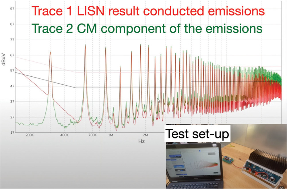
(See a video demonstration at https://youtu.be/70xhHsDk_M4?si=pf3p_q_63UCQEuAC)
To simplify for EMC engineers who don’t design power converters: a control loop, often consisting of a feedback loop (typically a voltage loop) and/or a feedforward loop (often a current loop), is designed to stabilize the circuit so the power converter can supply well-regulated power under various load conditions. These loops ensure stable operation even with step changes in load. Power electronics engineers design the loop based on the power converter circuit’s transfer function together with the filter transfer function.
As usual, a filter design must also meet size, weight, and, perhaps most importantly, cost requirements.
Having spent four years developing such switching schemes myself, I have mixed feelings about them. On an academic level, the idea is certainly sound. However, I have rarely seen such schemes used in industrial applications for various reasons. Perhaps the benefit of using a complicated switching scheme is compromised when it comes to real-life engineering. The complexity of implementing such schemes (not so much in computing power, but in ease of implementation for engineers) is also a reason why they are not popular.
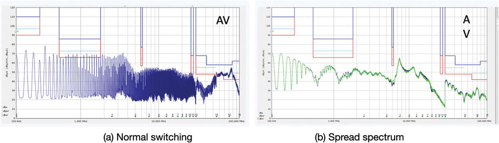
Spread spectrum can be implemented even in the simplest converter topology (such as a buck converter). The idea of not using a fixed switching frequency spreads the energy out, resulting in reduced signal measured in any one bandwidth. It should be noted that such techniques can either result in low-frequency noise improvement or high-frequency noise suppression, sometimes both, depending on the software schemes that engineers employ.
Figure 7 demonstrates the conducted emission improvement a spread spectrum technique can achieve on a dual active bridge-based DC-DC converter.
In the past, active filters were primarily used to counter low-frequency magnetic fields [11]. One could also say that the power factor correction technique, widely used in AC-DC applications, is also a form of active filter. Attempts were made to address higher frequency spectra (both conducted and radiated regions), but they never gained traction. In the year 2023, Texas Instruments introduced active filter solutions for both single and three-phase industrial applications [12], detailed in [13]. We are still waiting for more case studies on this chip, and I personally plan to work with it to assess its potential.
Other techniques are also available, forming part of my ongoing research, which I hope to share with the audience in the near future. In conclusion, I believe active filters will eventually find their market, given the advancements in technology.
- Mark J. Nave, Power Line Filter Design for Switched‑Mode Power Supplies.
- Keith Armstrong, EMC Design of Switch-Mode Power Converters (1-day course).
https://www.emcstandards.co.uk/files/g2_one_day_good_emc_techniques_for_motor_drives_switch-mode_etc.pdf - Timothy Hegarty, Texas Instruments, An Engineer’s Guide to Low EMI in DC/DC Regulators.
https://www.ti.com/lit/eb/slyy208/slyy208.pdf - Ken Javor, “Line Impedance Stabilization is in its Seventieth Year and Still Going Strong,” In Compliance Magazine, June 2023.
https://incompliancemag.com/line-impedance-stabilization-is-in-its-seventieth-year-and-still-going-strong - Onfilter, Power Line Communication (PLC): Measurements and Filtering the Signals.
https://www.onfilter.com/_files/ugd/53be97_42d43efb154e43ae8d39dab4cf5c58df.pdf - Robert W. Erickson, Dragan Maksimović, Fundamentals of Power Electronics, Second Edition.
- Ken Javor, “Seventy Years of Electromagnetic Interference Control in Planes, Trains, and Automobiles(and Ships and Spaceships, as well),” In Compliance Magazine, May 2023. https://incompliancemag.com/seventy-years-of-electromagnetic-interference-control-in-planes-trains-and-automobiles-part1
- Min Zhang, “GaN/SiC Transistors for Your Next Design: Fight or Flight?” In Compliance Magazine, October 2023. https://incompliancemag.com/gan-sic-transistors-for-your-next-design-fight-or-flight
- Min Zhang, “Troubleshooting Low-Frequency Common Mode Emissions,” Signal Integrity Journal, February 2023.
https://www.signalintegrityjournal.com/articles/2965-troubleshooting-low-frequency-common-mode-emissions - TI application note TPSM63603.
https://www.ti.com/lit/ds/symlink/tpsm63603.pdf - Min Zhang, “Low Frequency Magnetic Fields in Electric Vehicles,” In Compliance Magazine, April 2022. https://incompliancemag.com/low-frequency-magnetic-fields-in-electric-vehicles
- TI pioneers the industry’s first stand-alone active EMI filter ICs, supporting high-density power supply designs, Texas Instruments.
https://news.ti.com/2023-03-20-TI-pioneers-the-industrys-first-stand-alone-active-EMI-filter-ICs,-supporting-high-density-power-supply-designs - Timothy Hegarty, How Active EMI Filter ICs Mitigate Common-Mode Emissions and Increase Power Density in Single- and Three-Phase Power Systems, Texas Instruments. https://www.ti.com/lit/wp/slvafj9/slvafj9.pdf?ts=1721823249080

Zhang can be reached at info@mach1design.co.uk.