Editor’s Note: The paper on which this article is based was originally presented at the 2020 IEEE International Symposium on Product Safety Engineering held virtually in November 2020. It is reprinted here with the gracious permission of the IEEE. Copyright 2020, IEEE.
Part I of this paper, “Contact Burn Injuries: Part I: The Influence of Object Thermal Mass,” was reprinted in the May 2021 issue of In Compliance Magazine and is available at https://incompliancemag.com/article/contact-burn-injuries-the-influence-of-object-thermal-mass.
Part I of this series discussed the general aspects of the regulatory guidance for burn threshold surface temperature and contact duration limits [1,2,3]. Part 1 also outlined a number of important aspects associated with the regulatory framework. Specifically, the ISO 13732 standard assumes that the surface temperature of the object remains constant after contact with the tissue. The ASTM standard recognizes that there exists a difference between the object surface temperature, the object-skin interface temperature, and skin contact temperature, which is defined as the temperature at the epidermis-dermis interface. All the standards assume the surface temperature of the touched object remains constant and neglect the surface temperature reduction associated with the transfer of energy from the object to the tissues. Furthermore, only a limited number of contact parameters are considered in the standard. They include the thermal resistance between the heat source and surface of the device and the influence of the surface finish and material.
Part I outlined the limitation of the regulatory framework associated with long contact times where, according to the standards, a burn injury is always predicted regardless of material, finish, or other factors such as the object’s size [4]. This “infinite” contact time limit is demonstrably not valid for cases where the contacting object (and its surface temperature) cools due to the heat transfer to the skin. This is particularly true for low thermal mass objects and long-duration exposures. Part II addresses some of the additional limitations of the regulatory standards regarding the impact on the time-temperature contact burn threshold of the object size and shape (i.e., large, circular, elongated), contact resistance with the skin, and presence of an applied heat flux. The influence of object shapes and applied heat flux is of particular interest for the consumer electronics and wearable devices industry.
The methodology followed in this study is largely similar to that discussed in Part I [4]. The thermal damage assessment is based on the tissue temperature and the duration of the thermal exposure and is estimated using the concept of cumulative equivalent minutes at 43°C (CEM43°C) [5]. This model allows time-temperature history to be converted to an equivalent duration exposure at 43°C as:

where CEM43°C is the cumulative equivalent minutes at 43°C, t is the duration of the thermal exposure, R is a constant (R (T<39°C)=0, R(T<43°C)=0.25, R(T>43°C)=0.5) and T is the temperature at the tissue. Large tissue-specific databases are available in the literature that summarizes the relation between CEM43°C values and the observed damages to the tissues. In the case of the skin, most of the CEM43°C threshold values are based on the work of Henriquez and Moritz [6]. In this study, a 600 min CEM43°C for thermal damage threshold has been used as defined by the scientific literature [6].
In order to understand the influence of the object contact conditions on the propensity to cause a skin burn, a 2D heat transfer model was developed. As described in Part I, the model solves for the conduction of heat from a hot contacting object into human tissue layers. The Pennes bioheat equation [7], shown in Equation 2, is numerically solved to simulate the evolution of the temperature distribution through the skin. The Pennes bioheat equation accounts for blood perfusion, in which blood flow through the skin carries heat away from the contact area and metabolic heat generation effects in the dermal and hypodermal layers of the skin. The computational model integrates for CEM43°C as indicated in Equation 1.
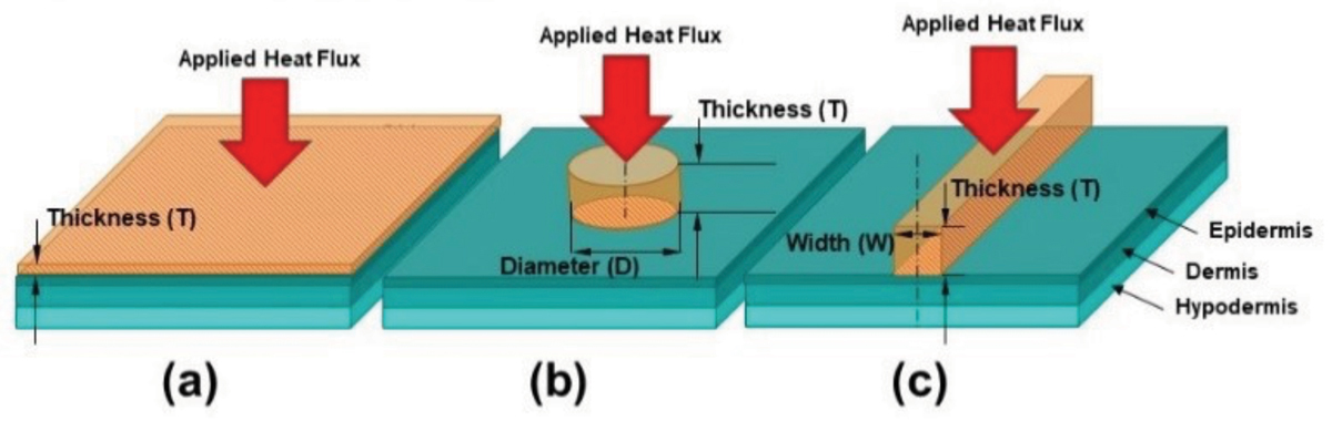
The model developed for this study was used to simulate the three geometry configurations shown in Figure 1. The first configuration is that of an infinite plate of a finite thickness which is also referred to as a large contact area. The second configuration is that of a cylindrical object contacting the skin to create a circular contact area. The third configuration is that of an infinitely long rectangular object of finite thickness and width in contact with the skin creating an elongated contact area.
In these computations, an object of finite thickness is placed into contact with the skin which is composed of epidermis, dermis, and hypodermis. The contact between the hot object and the skin is assumed to have zero contact resistance unless otherwise stated. The non-contacting surfaces of the hot object are considered to be adiabatic unless otherwise stated in order to provide conservative results. Multiple computations with varying initial object temperatures are carried out for several materials, object thicknesses, shapes, and sizes. The influence of active components that dissipate energy has been simulated as a heat flux boundary condition that is applied on the object surface that is opposite to the contact surface, as shown in Figure 1. In the heat flux scenarios, at time equal 0 sec, an object of uniform temperature comes into contact with the skin surface simultaneously with the application of the heat flux. Burn injury thresholds based on initial object temperature, exposure time, and thickness are shown and discussed in the Results section.
![Equation 2: Pennes bioheat equation [7]](https://digital.incompliancemag.com/asset/2022/04/ic-may-22-contact-burn-injuries-part-2-eq2.jpg)
As discussed in Part I, the model was validated using the experimental data of Henriques and Moritz [6] and Stoll and Green [8]. The model shows that temperature and contact durations that result in a CEM43°C of 600 min, a burn threshold suggested by the literature, are well aligned with all the relevant experimental observations from Henriquez and Moritz [6] and Stoll and Green [8]. The interested reader should refer to Part I of this study for more details on the validation procedure.
The following variables and corresponding ranges have been considered in the sensitivity studies summarized in this paper:
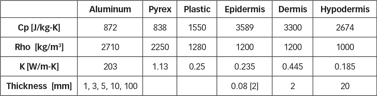
- Material of the contacting object: Aluminum, Pyrex, Plastic (Table 1 summarizes the thermal properties of the plastic material considered in this study)
- Thickness of the contacting object: 1 mm, 2 mm, 3 mm, 5 mm, 10 mm, and 100 mm
- Shape of the contacting object: large contact area, circular contact area, elongated contact area (see Figure 1)
- Size of the contacting object: for circular contact areas: diameters of 1 mm, 3 mm, 5 mm, and 10 mm; for elongated contact areas: widths of 1 mm, 3 mm, 5 mm, and 10 mm
- Contact resistance: 0 m2K/W, 10-6 m2K/W, 10-4 m2K/W, 5×10⁻⁴ m2K/W, 10-3 m2K/W [9]
- Heat Flux from active components: 0 W/m2, 50W/m2, 100 W/m2, 200 W/m2, 400 W/m2
The sensitivity of the burn threshold to various contact conditions is conducted by tabulating the time it takes for the basal layer of the skin to reach a CEM43°C of 600 minutes. The results are presented in a format that is similar to the ISO 13732 standard. The analysis has been performed for a range of initial object temperatures from 130°C-43°C. The isolines of 600 min CEM43°C are plotted on an initial object temperature to time to 600 min CEM43°C plot.
Sensitivity to material properties and contact object thickness is studied using the large contact area configuration. The chosen object thicknesses were 100 mm, 10 mm, 5 mm, 3 mm, and 1 mm. Isolines of CEM43°C equal to 600 min are plotted as functions of initial object temperature and time in Figure 2, showing three sets of curves (1) red curves for plastic objects, (2) black curves for ceramic objects, and (3) blue curves for metal objects. The material properties that were considered for the object and skin are summarized in Table 1.
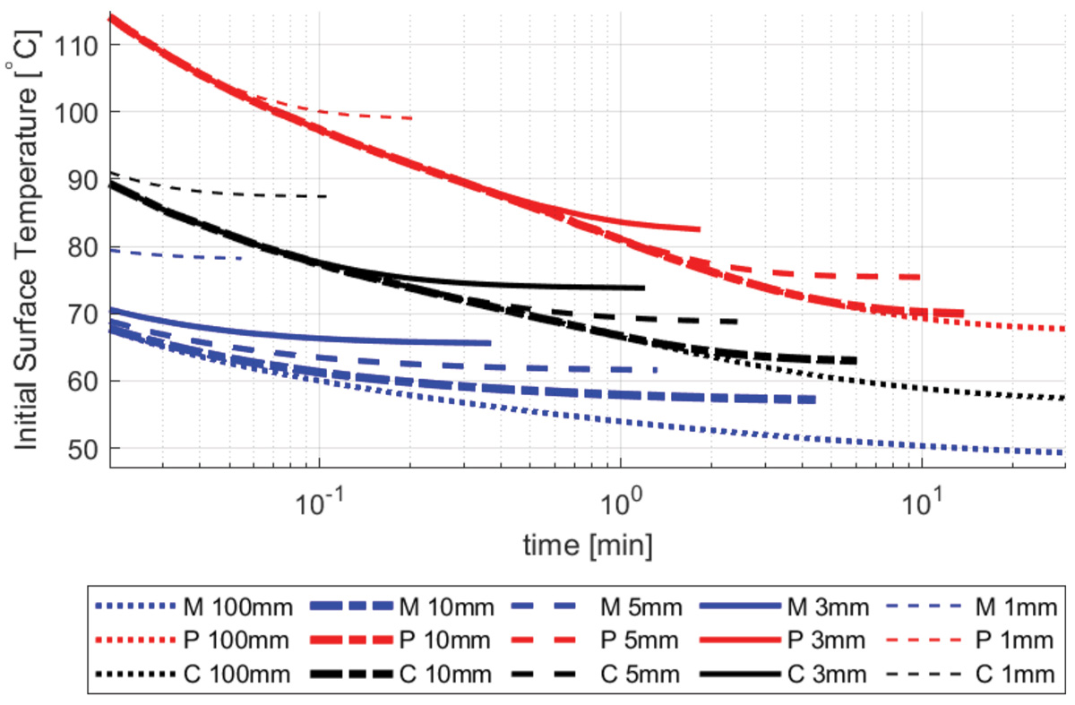
For a specified thickness, the plastic objects have the highest burn thresholds, followed by ceramic objects and metal objects. This is due to the thermal conductivity of each material. Higher material conductivity leads to a larger heat transfer into the skin resulting in higher skin temperatures and lower burn thresholds. For a given material, the curves approach one another for short contact duration scenarios where the objects behave as thermally thick. As contact duration increases, the curves diverge, with thinner objects having a higher burn threshold due to their lower thermal mass. For instance, in order to cause a burn for a 1 min contact duration, a 100 mm and a 1 mm thick metal plates must have an initial temperature of 54°C and 78°C, respectively.
The burn threshold curves displayed in Figure 2, and those summarized in the ISO 13732 standard, feature the same trends with respect to the material property and the same general relation between contact duration and initial temperature. That is, when the contact duration decreases, the object temperature required to cause burn injury needs to increase. However, the ISO 13732 standard shows that, as contact duration increases, the curves for metal, ceramic, and plastic converge to a condition where, regardless of the material of the object, a burn injury will occur if the object has a surface temperature exceeding 43°C. In ISO 13732, it is assumed that the “surface temperature is essentially maintained during the contact period either by the mass of the product or by a heating source” [1]. This is not a realistic assumption for semi-infinite objects, let alone for objects of finite mass, unless there is a heat source that actively maintains the object surface temperature. Furthermore, it can be noted that the last point in each curve represents a temperature threshold at which an object of that material and thickness is able to cause a skin burn. If the initial object temperature is lower than this threshold, there is not enough energy stored in the object to cause a skin burn, and as a result, the contact time required to incur a burn at that temperature becomes infinite.
A sensitivity analysis of the contacting object shape and size was performed to understand their effects on the potential for thermal damage to the skin. First, the effect of contact area size is examined by modeling circular contact areas of various diameters. Next, we examine elongated contact areas of varying widths.
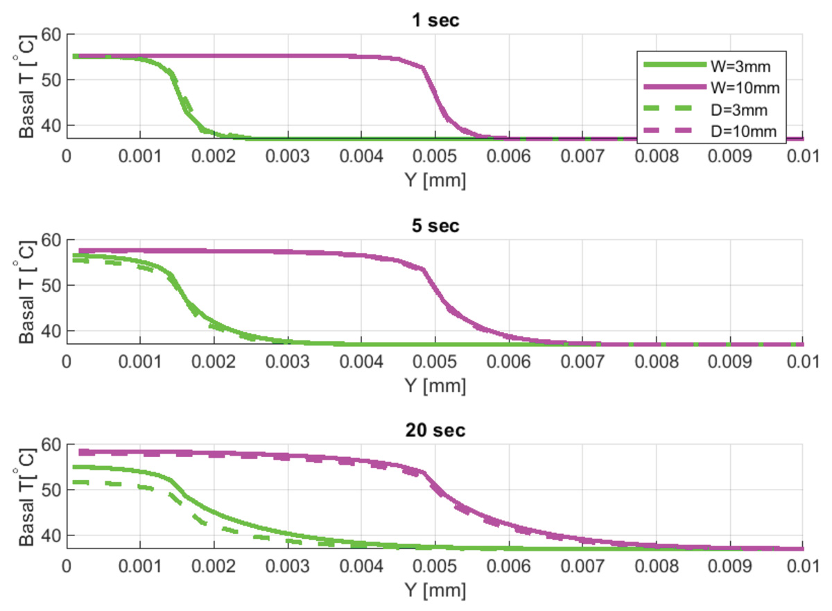
Figure 3 shows the basal temperature profiles at three different times for a circular contact area with a diameter of 3 mm and 10 mm and for an elongated contact area with a width of 3 mm and 10 mm. Both contact areas correspond to a ceramic object that is 100 mm thick with an initial temperature of 80°C.
The results for the two circular contact shapes (see dashed lines in Figure 3) at 1 sec indicate a maximum basal centerline temperature of approximately 55°C. The basal temperature immediately outside of the contact area also increases as heat diffuses radially through the skin. At 5 sec, the contact with the 10 mm and 3 mm diameter objects results in a centerline temperature of 57°C and 56°C, respectively. Both basal temperature profiles flatten out as heat continues to diffuse radially into the skin. As expected, these edge effects are more pronounced for the 3 mm diameter object.
Figure 3 shows elongated contact areas with 3 mm and 10 mm widths as solid lines. At 1 sec, the elongated contact area results closely match the circular contact area basal layer temperature data. At this point in time, all objects still behave as thermally thick, and as a result, the influence of the geometric contact parameters is minimal.
At 5 sec, basal temperatures associated with the elongated contact areas are higher than the circular contact area temperatures. At 20 sec, the effects of both the size and shape are even more pronounced with (1) the elongated contact temperatures being higher than the circular contact temperatures and (2) the larger contact temperatures being higher than the smaller contact temperatures. Higher basal layer temperatures are observed for elongated objects in comparison to a circular object of the same characteristic size (i.e., diameter for circular contact area, width for elongated contact area) due to the absence of the heat diffusion through the skin in the direction aligned with the elongated object.
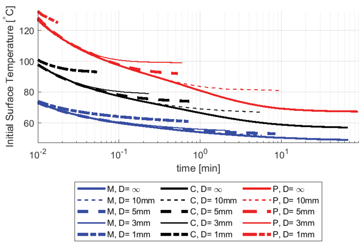
In Figure 4, isolines for CEM43°C equal to 600 min are shown for cylindrical objects with diameters of 1 mm, 3 mm, 5 mm, and 10 mm. The infinite contact diameter scenario (i.e., identical to the large contact area case for a 100 mm thick object seen in Figure 2) is also shown. Decreasing the diameter of the contact area decreases the overall heat transfer into the skin, increasing the burn threshold temperatures.
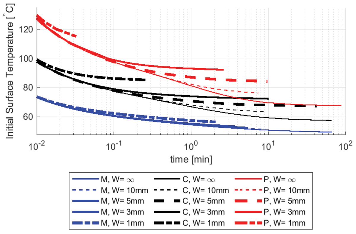
Figure 5 shows the isolines for CEM43°C equal to 600 min for elongated objects with widths of 1 mm, 3 mm, 5 mm, and 10 mm. The infinite contact width scenario (i.e., identical to the large contact area case for a 100mm thick object seen in Figure 2) is also shown. The results summarized in Figure 4 and Figure 5 confirm that for the same material and characteristic size, the elongated contact area scenarios have lower burn thresholds than their circular counterparts.
The effect of the circular and elongated contact areas was studied by holding the diameter/width constant and by varying the thickness of the object. In Figure 6, isolines of CEM43°C equal to 600 min are shown for circular contact areas with a diameter of 5 mm and thicknesses of 1 mm, 2 mm, 3 mm, 5 mm, 10 mm, and 100 mm. Similar to the trend seen in Figure 2, the curves for a particular material approach each other with decreasing contact duration. For burn thresholds found at shorter contact durations, the dominant factor is the high initial temperature of the object.
Furthermore, as the object thickness decreases, the burn temperature threshold increases due to the lower object thermal mass. This trend can be seen for both ceramic and metal objects, even though it is more pronounced for the former.
It should be noted that a low object thermal conductivity results in lower rates of heat transfer into the skin and, therefore in a slower decrease in the object’s internal temperature. For example, in the plastic circular object cases shown in Figure 6, the low thermal conductivity of the plastic limits the heat transfer rate, and the curves fall on top of each other for all objects with thickness larger than 2 mm. In all these scenarios, the rate of heat transfer through the objects bottlenecks the heat transferred to the skin, and only at a thickness of 1 mm or less does the thermal mass of the object becomes small enough to be the limiting factor that controls the burn threshold.
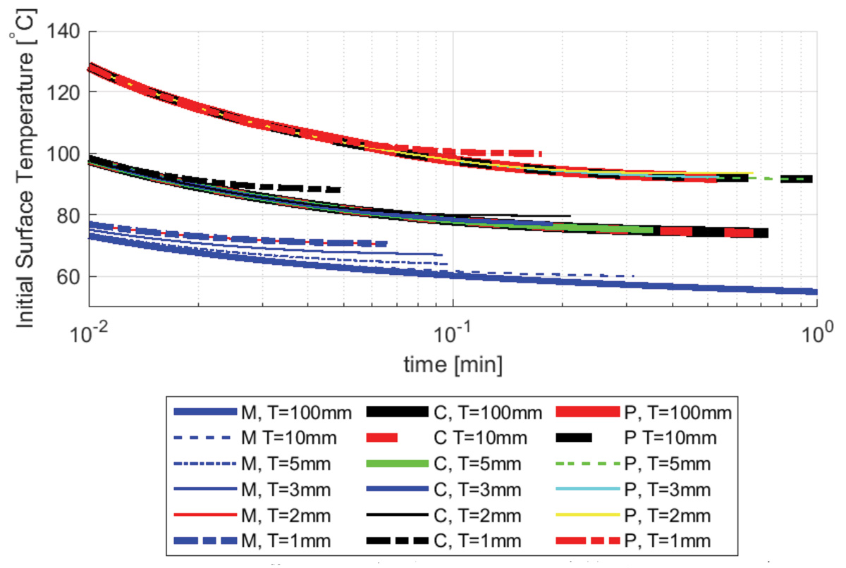
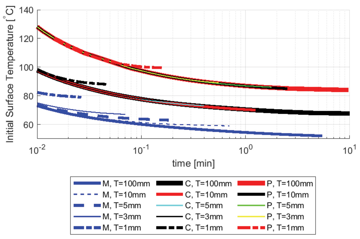
Figure 7 shows the isolines of 600 min CEM43°C for elongated contact areas with a width of 5 mm and thicknesses of 1 mm, 3 mm, 5 mm, 10 mm, and 100 mm. The trends are similar to those seen in Figure 2 and in Figure 6.
Thus far, only objects with an initial uniform temperature with adiabatic non-contacting surfaces have been discussed. However, objects may also contain a heat source such as a processor, as is now common in consumer electronics. The effect of the heat flux is examined here by imposing a uniform heat flux of 400 W/m2, 200 W/m2, 100 W/m2, 50 W/m2, and 0 W/m2 on the face of the object that is not in contact with the skin. Figure 8 shows the 600 min CEM43°C isolines for large contact area metal objects that are 5 mm thick. The case of zero heat flux is the same as found in Figure 2. Increasing the imposed heat flux decreases the burn temperature threshold as it establishes a non-zero baseline heat flux into the skin over time. In the cases analyzed earlier in the paper, the baseline heat flux became zero after the initial transient effects associated with the temperature differential between the skin and the contacting object.
At short contact durations, the effect is not as pronounced as the vast majority of the heat flux into the skin is driven by the high object surface temperature differential. Additionally, the effect on the basal layer by the imposed heat flux is delayed by the time it takes to establish the corresponding temperature gradient between the object and epidermis as well as within the object itself. At a contact duration of 10 minutes, the burn threshold for a 5 mm metal plate without applied heat flux is reached with an initial object temperature of approximately 62°C. When a flux of 400 W/m2 is applied, the burn threshold at 10 minutes is reached when the initial temperature of the object is approximately 60 °C. The influence of the heat flux becomes more pronounced as the contact duration increases past 10 minutes, which is a relevant contact scenario for the consumer electronics and wearable industries.
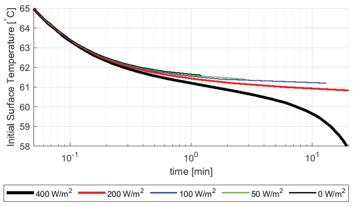
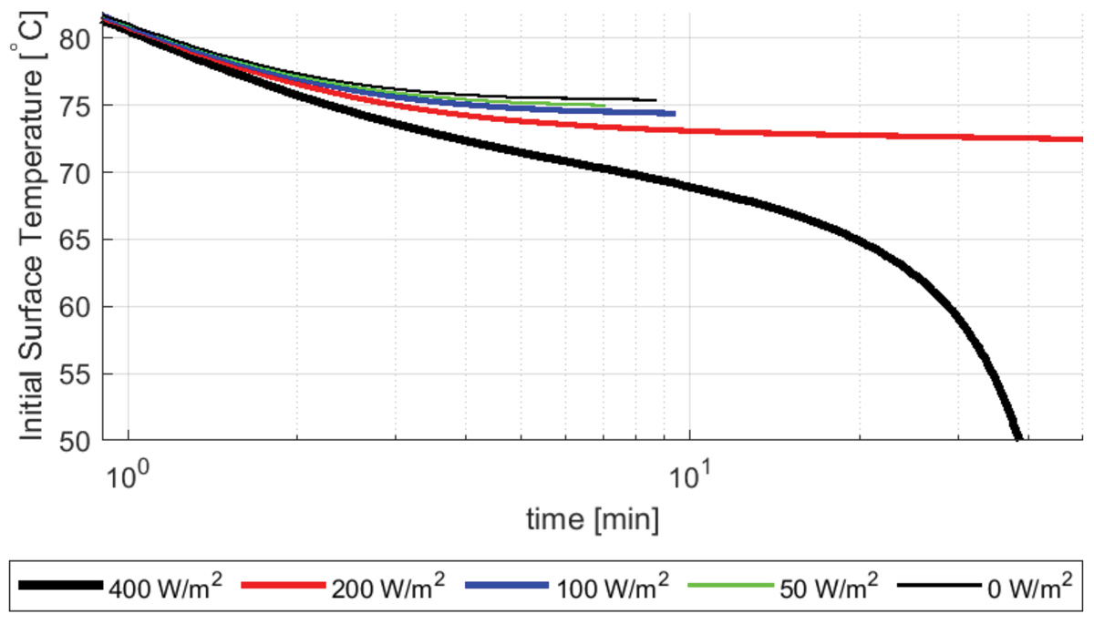
Figure 9 shows the 600 min CEM43°C isolines for 5 mm thick large plastic plate. Much like the metal counterparts in Figure 8, the effects of the imposed heat flux are more pronounced at longer contact durations. At 10 minutes, the 5 mm thick plastic plate without applied heat flux reaches the burn threshold with an initial object temperature of approximately 75.4 °C. The same plate with a 400 W/m2 heat flux reaches the burn threshold at 10 minutes with an initial temperature of approximately 69 °C.
All the previous results are based on the assumption of perfect contact between the skin and the contacting objects (i.e., zero contact resistance scenarios). However, small gaps in the interface between the contacting objects due to surface roughness cause a temperature drop across the interface. This phenomenon is typically addressed by including a contact resistance between the objects. Generally, lower contact pressure and higher surface roughness result in higher contact resistance. In the context of contact skin burns, contact resistance values as high as 10-3 m2K/W are considered possible [9].
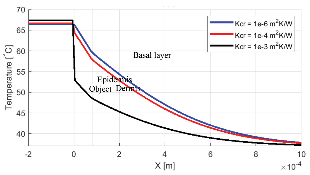
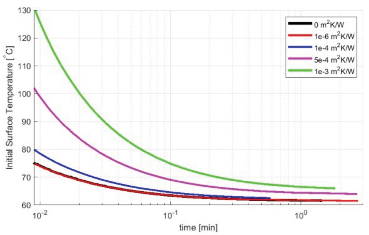
Figure 10 shows the centerline temperature profile for 5 mm thick objects with a large contact area, an initial temperature of 70°C, and contact resistances of 10-6, 10-4, and 10-3 m2K/W. At 1 sec, the 10-6 m2K/W contact resistance case reaches a basal layer temperature of 60°C, whereas the 10-3 m2K/W contact resistance case reaches a basal layer temperature of 48°C. This indicates that contact resistance plays a major role in determining the amount of heat that is transferred to the skin.
The effect of contact resistance on the burn injury temperature thresholds is shown in Figure 11. Contact resistances between 0 m2K/W and 10-3 m2K/W are applied to the interface between the skin and a 5 mm thick metal object with a large contact area. For an initial object temperature of 80°C, contact resistances of 10-4 m2K/W, 5×10⁻³ m2K/W, and 10-3 m2K/W result in a time to a CEM43°C equal to 600 min of 0.5 sec, 1.5 sec and 3.6 sec, respectively. The analysis also shows that the results obtained for the case with no contact resistance are substantially similar to the 1e-6 m2K/W contact resistance case. For long contact durations, the influence of the threshold temperature tends to decrease.
Guidance on contact burn temperature threshold found in the current regulatory standards fails to account for the importance of thermal mass, geometry of the contact, and the presence of heat dissipation of active components. This paper employs a numerical model that solves the Pennes bioheat transfer equation to predict the contact burn thresholds. This framework was described and validated in an earlier work [4]. This study describes a large set of sensitivity studies for factors that control the burn temperature threshold such as (A) material properties, (B) contact shape, (C) contact thickness, (D) heat flux, and (E) contact resistance. The study shows that there is an initial temperature above 43°C for objects of a finite thermal mass where a burn injury will not occur regardless of the contact duration. This initial object temperature is dependent on the geometry, dimensions, material properties, and contact resistance of the contacting object. Future work will include developing simplified procedures based on regression models or physical scaling that can be used to readily estimate the time-temperature thresholds associated with contact burns and accounts for the effect of the relevant parameters including but not limited to those addressed in this study.
- International Organization for Standardization, (2006), “Ergonomics of the thermal environment – Methods for the assessment of human responses to contact with surfaces – Part 1: Hot surfaces (ISO 13732- 1:2006),” Retrieved from http://www.iso.org/standard/43558.html
- ASTM Standard 1057, 2017, “Standard Practice for Determination of Skin Contact Temperature from Heated Surfaces Using a Mathematical Model and Thermesthesiometer,” ASTM International, West Conshohocken, PA, 2017.
- ASTM Standard 1055, 2014, “Standard Guide for Heated System Surface Conditions that Produce Contact Burn Injuries,” ASTM International, West Conshohocken, PA, 2014.
- M. Yen, F. Colella, H. Kytomaa, B. Allin, A. Ockfen, “Contact Burn Injuries Part I: The influence of object thermal mass,” Proceedings of the 2020 IEEE Symposium on Product Compliance Engineering, SPCE 2020, November 16-17, 2020.
- S. A. Sapareto, W.C. Dewey, “Thermal dose determination in cancer therapy,” Int J Radiat Oncol Biol Phys, 1984;10:787–800.
- A.R. Moritz, F. C. Henriques, “Studies of Thermal Injury: II. The Relative Importance of Time and Surface Temperature in the Causation of Cutaneous Burns,” Am J Pathol, 1947 Sep; 23(5):695-720.
- H. H. Pennes, “Analysis of Tissue and Arterial Temperature in the Resting Human Forearm,” J. Appl. Physiol., vol. 1, pp. 93-122, 1948.
- A. Stoll, L. Greene. “Relationship between pain and tissue damage due to thermal radiation.” J Appl Physiol 1959; 14: 373–82.
- A.P. Hatton, H. Halfdanarson, “The Role of Contact Resistance in Skin Burns,” J. Bio Engr, vol. 4, issue 2, pgs. 97-102, 1982.