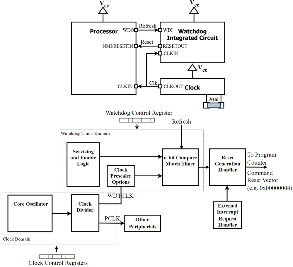
atchdogs have long been a standard, if slightly esoteric, element of system design, often receiving only secondary consideration after the primary application has been planned out. At their core, they serve a straightforward purpose: providing a graceful means of recovery in the event of abnormal system behavior. At their origin, watchdog timer architectures were simple, implemented via a dedicated application-specific integrated circuit (ASIC), positioned adjacent to the system’s processor (see Figure 1).

- The system watchdog must be able to operate independently, mitigating the risk of dependent failures between the device being protected and the device doing the protecting and
- The system watchdog must be capable of accurately monitoring the timing of individual tasks and reporting a hung task to a higher-level application, all while remaining fault tolerant, allowing for maximum uptime.
In the following sections, we’ll first trace the evolution of watchdog timers, starting with the basic refresh mechanism, moving on to windowed watchdogs, and finally examining challenge-response (Q&A) watchdogs, complete with real-world application examples. We’ll then delve into safety analyses, explore various system architectures showing how multiple watchdogs can coexist in a robust design, and ultimately highlight the key reporting features to look for when selecting a watchdog solution. This holistic approach will equip you with a comprehensive understanding of modern watchdog systems and how they’re meeting the demands of functional safety in increasingly complex, multicore environments.

Key features of this basic watchdog include:
- Edge-triggered input: Responds to rising edges, falling edges, or both
- Programmable timeout: Defines how much time may pass between refresh events and
- Reset delay (or grace period): Specifies the time from a missed refresh to an actual reset.
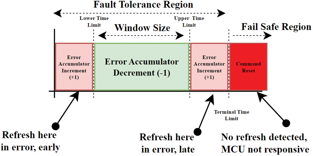
To address the need for more precise timing checks, the next evolution introduces the window-based watchdog.
- Lower time limit: If the refresh comes early, the watchdog flags an error
- Upper time limit: If the refresh comes late, the watchdog flags an error and
- Terminal limit: Much like the basic watchdog’s timeout, this defines the point at which the system will be reset if no valid refresh is seen; this is often referred to as too late or non-responsive time limit.

- Granular fault tolerance: You can configure different potential responses based on whether the refresh was too early or too late, potentially allowing the system to log errors and continue running for minor timing violations and
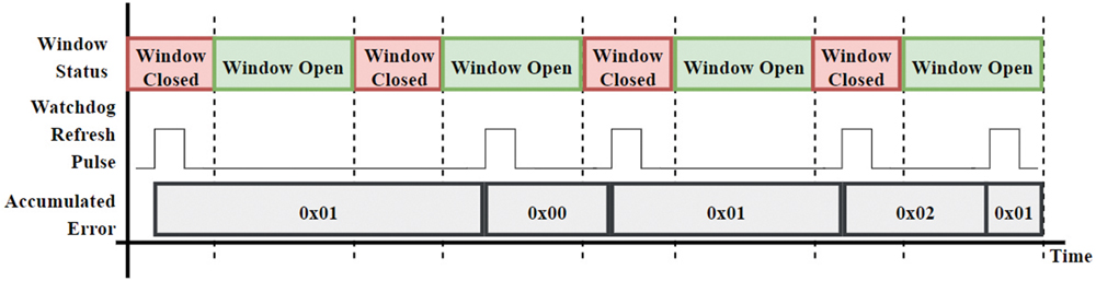
- Monitoring task health: Some designs allow you to keep track of how often these individual limits are breached. A higher-level supervisor could read an “error count” register and spot if certain tasks are chronically missing their timing. Over time, this data helps diagnose performance bottlenecks or failing components.
- Setting the three-time limits: Specified in base clock counts or milliseconds and
- Defining an error tolerance: An “error accumulator” or similar mechanism (Figure 5) decides how many errors trigger a reset.
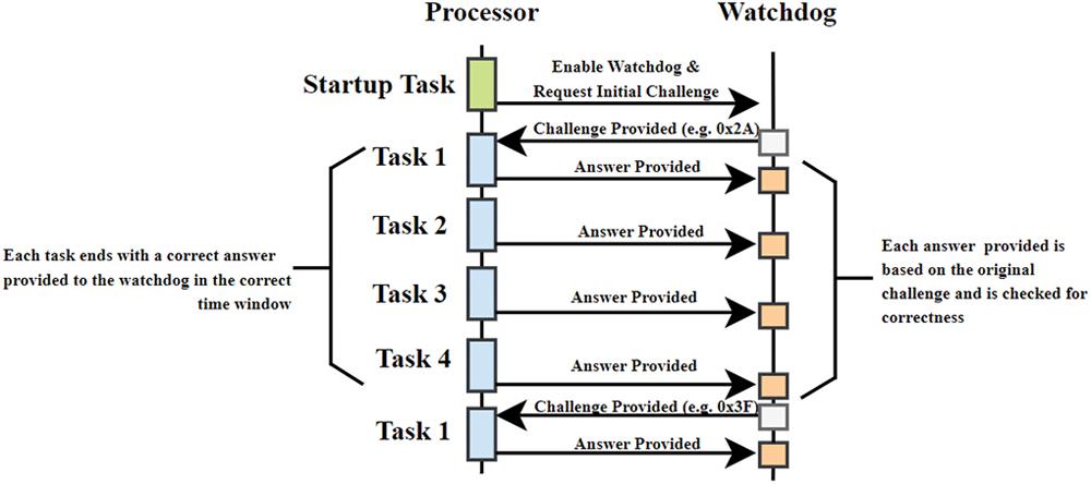
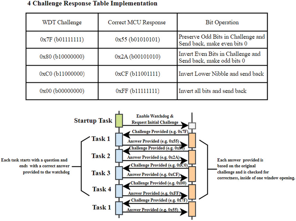
- 4-question-and-answer (4QA): The watchdog provides four sequential challenges (often simple operations on an 8-bit value), and each must be answered correctly in the right time window (see Figure 8).
- 16-question-and-answer (16QA): The watchdog uses a seed token that defines the next four responses. Additional seeds can chain together to create longer challenge sequences (see Figure 9). This allows for more in-depth program-flow monitoring across multiple tasks.
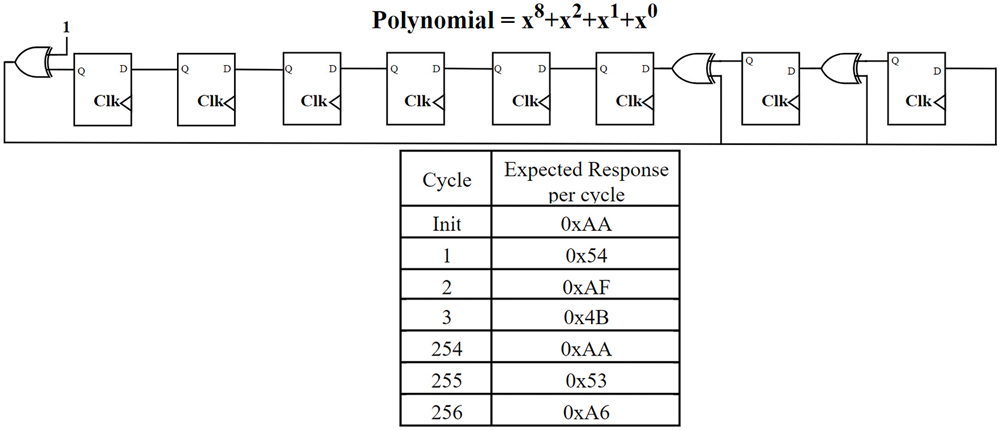
- LFSR (linear feedback shift register)–based: A polynomial is used to generate a pseudo-random challenge (Figure 10). The monitored device must compute the correct response for each step in the sequence. This approach can create a large number of possible challenge-response pairs, further increasing system robustness.

- Program flow verification: Ensuring tasks and subroutines execute in the proper sequence and
- Advanced error accounting: An error accumulator or register can keep track of how many challenges were missed or answered incorrectly, letting the system react gracefully to minor issues while still triggering a hard reset when conditions warrant it.
- The safety analysis of relevant fault types
- The avoidance of undesirable system dependencies
- The proper integration of multiple watchdogs (if necessary) and
- The selection of reporting features that align with the application’s diagnostic needs
- The first relates to random hardware faults, such as an oscillator becoming stuck or running at an incorrect frequency or issues arising from miscounted edges on a communication interface like I2C or SPI.
- The second concerns systematic failures, where tasks fail to execute correctly because of software defects—examples include memory corruption due to an errant pointer or semaphore mismanagement that leaves a task waiting indefinitely.

Although these two categories illustrate typical random and systematic errors, a thorough failure mode, effects, and diagnostic analysis (FMEDA) is recommended to examine the system’s fault modes. The diagnostic analysis portion of this activity often identifies coverage the watchdog can provide to a specific subsystem. For example, a challenge-response watchdog can address more sophisticated problems by verifying correct arithmetic operations, monitoring individual cores in a multi-core architecture, and detecting clock-frequency irregularities or hardware communication issues as opposed to a simple windowed response watchdog. In general, the watchdog is expected to catch single-point faults that might otherwise violate the system’s safety goals.
Achieving this level of protection requires that the watchdog remains free from dependencies that could prevent it from detecting application errors. A dependent failure analysis (DFA) helps uncover situations where the watchdog relies on shared resources or design elements that might also be subject to failure. In Figure 12, the core oscillator and clock divider provide one clock domain to the peripherals, core, and watchdog timer. Additionally, all system memory is shared, as well as all powered from one power domain. Failure in any one of these areas would prevent the WDT from functioning properly in addition to impacting the ability of the device to achieve the safety goal.

- Use an independent clock source that remains unaffected if the main system clock fails
- Maintain reliable power or voltage supervision so that it does not lose state information during dips or brownouts and
- Operate offboard, which keeps it isolated from defects in the MCU pipeline or CPU core and ensures that it continues running even when the MCU is compromised.

Examining Watchdog Architectures
This situation is best found in applications with watchdogs per core on a multicore processor and an offboard watchdog either on an associated PMIC or voltage monitor integrated circuit. To start this design, the watchdogs are separated into two groups: the subordinate watchdogs found on a per-core basis and the master watchdog found offboard (see Figure 14).

- Clock independence: The external master watchdog relies on its own clock source. If any single core’s clock fails, the core’s own watchdog stops refreshing, and eventually, the master sees an issue. This separation ensures that one domain’s fault does not compromise the entire watchdog infrastructure.
- Fault isolation: Each subordinate watchdog can trigger a localized reset or interrupt for its core. If that fails or the core remains hung, the master watchdog takes further action, like forcing a full power cycle.
- Resource separation: Subordinate watchdogs rely on the MCU’s internal registers and clock domains, while the master watchdog uses an offboard resource (such as a separate oscillator). This avoids the problem of a single clock or memory bus dominating the entire safety mechanism.

- Reduced downtime: Resetting a single peripheral requires less re-initialization time than rebooting the entire system, improving availability in real-time or mission-critical applications and
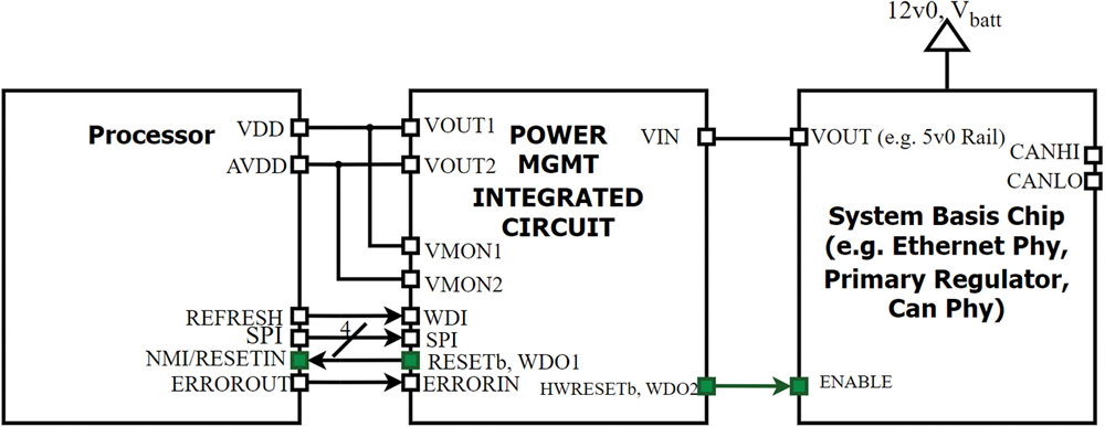
- Dual timeout domains: The shorter timeout for WDO1 (e.g., 100 ms) might be enough to catch process stalls. The longer WDO2 timeout (e.g., 500 ms) covers system-level lockups. While the watchdog remains decoupled from the processor clock domain, this also reduces the chance of a single clock failure compromising both outputs.
The key advantage here is that not only the clock but also the way to a safe system state is physically isolated from the processor’s main reset domain but still allows some fault tolerance in the case of a non-critical error.

At the co-processor layer, the device collects these signals and tracks their failures applying custom behavior allowing pin-based refreshing to lower-level tasks, and challenge-response type logic for higher-level, critical tasks.
Additionally, in this scenario, we gain the benefits of a dual watchdog output in addition to customizable reset requirements. Examples of these custom requirements are:
- This would allow the system to log a custom number of errors in different situations, resulting in increased uptime and visibility into which tasks have stalled or are otherwise causing system instability.
- Custom responses to reset specific physical interfaces. In an automotive module, there might be multiple interfaces (e.g., CAN, LIN, and an Ethernet PHY). Depending upon the task that is stalled, you may want to either cycle power to or otherwise disable a specific function while still offering reduced functionality (this is often referred to as failing functional).

Ideally, the system would offer a simple communication channel built into the boot loader (for example, CAN or LIN in automotive applications) to facilitate external queries about the reset cause. When done properly it aids engineers in finding the cause for reset by highlighting persistent errors.