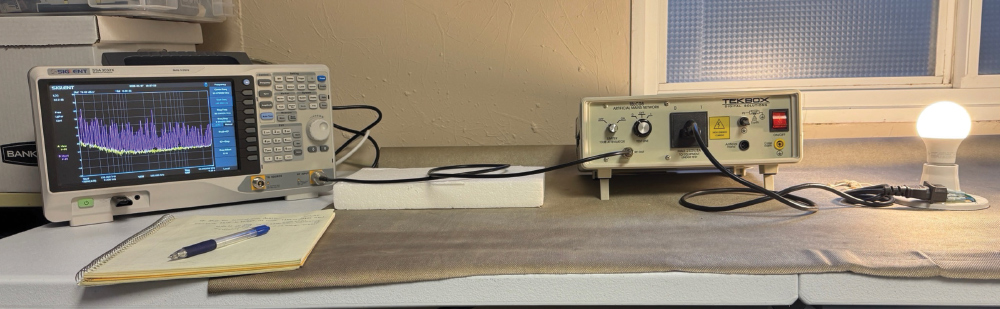
re-compliance testing aims to duplicate the test setup used by your third-party test lab. Fortunately, setting up a conducted emissions test in-house is relatively simple and can be performed on the benchtop (Figure 1).
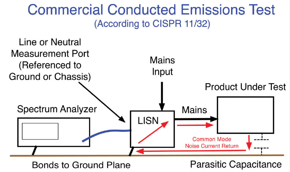
The purpose is to measure the noise voltages (as referenced to ground or chassis) for the line or neutral circuits. The return path for the common mode currents is shown, and we’ll discuss this in a later article.
First, let’s discuss the various noise voltages produced by common line-operated switch-mode power supplies. The conducted emissions test measures noise voltage EMI, that is, the emission voltages measured from line to ground (or chassis) and neutral to ground (or chassis). This is depicted in Figure 1 and is measured using a line impedance stabilization network, or LISN.
A typical conducted emission plot of a line-operated switch-mode power supply is shown in Figure 2. This was measured using an EMZER EMScope EMI receiver with built-in LISN.

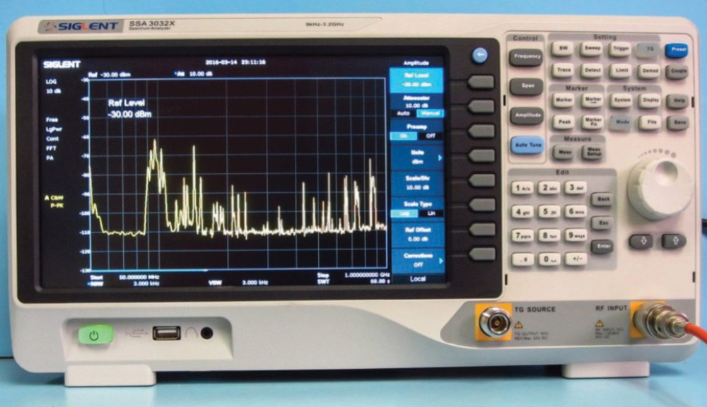
Spectrum Analyzer: Figure 3 shows an example of an affordable bench top spectrum analyzer. You’ll want to specify an analyzer with the required test frequency range as specified in the appropriate standards your product requires. Most of the conducted emissions tests will start from 10 kHz (military) or 150 kHz (Commercial) and stop to at least 30 MHz (10 MHz for military).
For commercial testing, this is not nearly as much an issue, but you’ll still see part of the peak (or associated skirt) at the 150 kHz start frequency. The lab-quality spectrum analyzers won’t generally have this issue due to better internal shielding. In the case of conducted emissions, you definitely get what you pay for.
The example in Figure 4 shows an expanded plot from 9 kHz to 1 MHz showing the zero-frequency peak with associated phase noise “skirt.” A Siglent SSA 3032X analyzer was used for the measurement. The marker at 150 kHz indicates the commercial starting frequency. Notice it’s riding on top of significant phase noise, which appears as a rise in the noise floor of the measurement. Typically, the measurement of switch mode power supplies will be relatively large at this low frequency, so this rise in noise floor may not really be an issue.
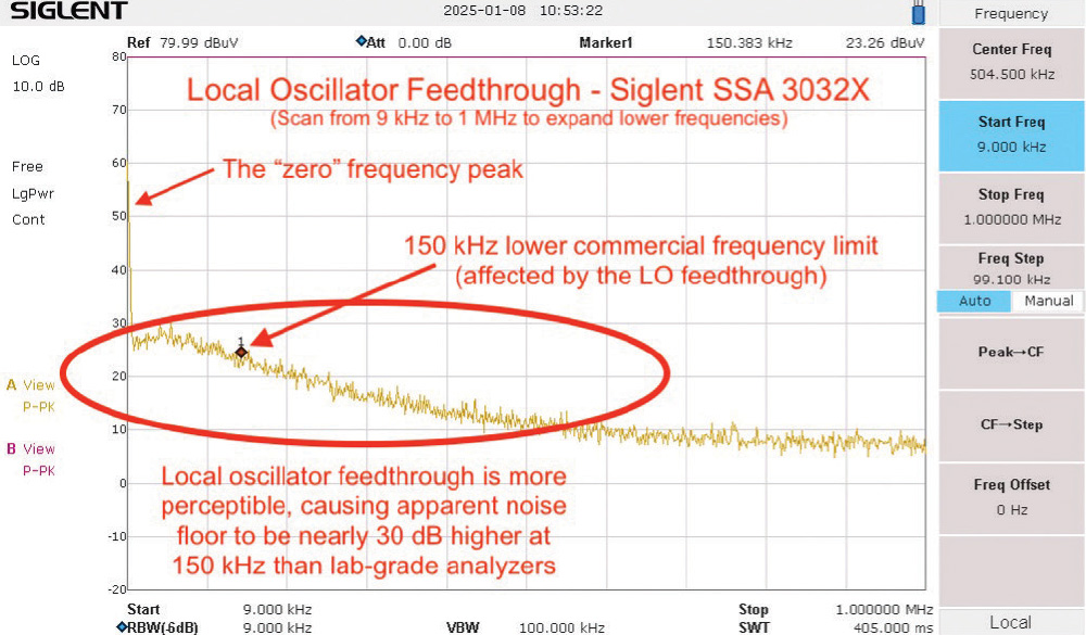
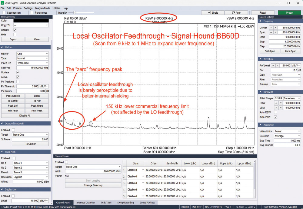
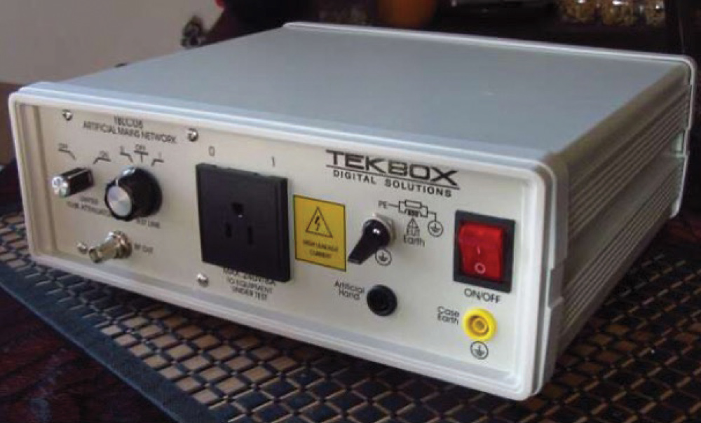
Figure 6 shows the LISN (Tekbox TBCL08) I like to use for AC line-operated products. It has a switch for line and neutral measurements and can handle up to 8 amps of line current.
Currently, I’m using a Tekbox model TBGP “roll up” ground plane over the top of my plastic table top. This comes in a 250 x 140 cm roll, and the 250 cm dimension nearly fits across my 6-foot table. I keep the excess rolled up behind the test setup. See Figure 7.
Transient Protector: A transient protector at the spectrum analyzer input is highly recommended to protect the sensitive RF front end from transients caused by applying or removing main power or when switching from line to neutral measurement. Many of these also include a 10-dB attenuator as extra protection. I like to use the Tekbox TBFL1.
- Wyatt, EMC Troubleshooting Trilogy (Volumes 1, 2 and 3)
- Saelig Electronics (U.S. distributor for Tekbox and Siglent products)
- Siglent Technologies
- Tekbox Digital Solutions
- Wyatt, “How to use spectrum analyzers for EMC,” In Compliance Magazine website, March 7, 2024.