


he current method of DC/AC analysis does not properly compute the DC input power to the inverter required to support electrical loads. The current methodology requires the DC power source be a battery or a fuel cell that can provide enough real power to the inverter to meet the load on the motor and this approach does not consider the reactive power component. What the theory is the DC power source must provide enough power to meet the motor apparent power needs and not just the real power needs. If the power calculations are inaccurate, then this will impact the battery powering the inverter and lead to improperly sized components and possible thermal issues.
A new power flow analysis is required to determine how much power needs to be provided to the inverter and motor, and a new approach is needed to compute component efficiency. A new method would provide a better understanding of losses and heat generation, which would also lead to a more robust electromechanical system.
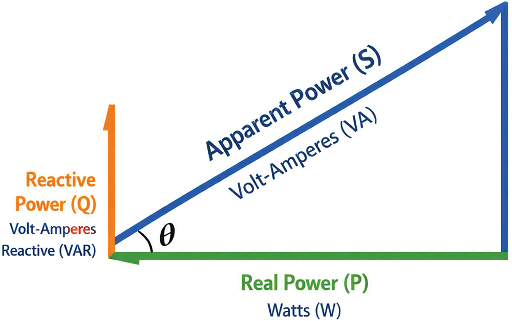
One of the fundamental rules of mathematics is that we can only add numbers of the same units; we can add mass to mass to get a combined mass. But, in the world of alternating current, we are adding real power, P(W), to reactive power, Q(VAR), to compute apparent power, S(VA), as shown in Figure 1.
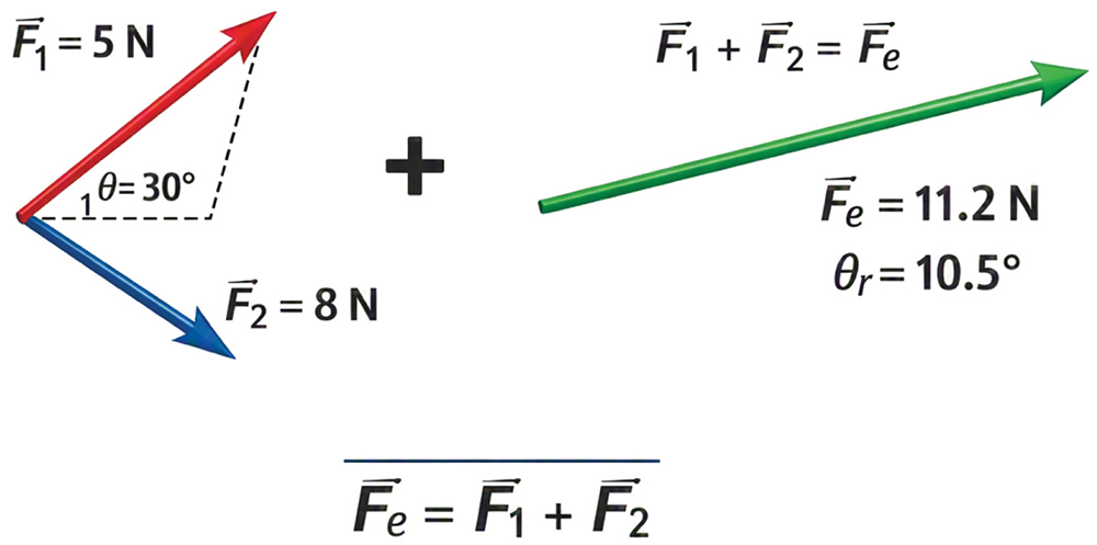
The conservation of energy applied to DC/AC systems, like the ones used in battery electric vehicles, can provide insight into mapping the power flow and heat losses in these systems.
Typically, a battery or a fuel cell will provide power to the inverter, which transforms the DC into AC, and the AC power is fed to the motor, as shown in Figure 3.
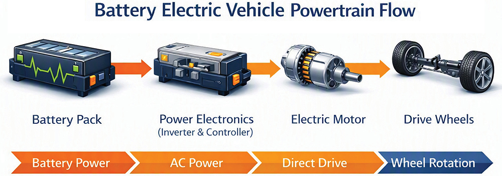


Once the inverter converts the DC to AC, the AC motor will take the electrical power and convert the electricity into torque and angular speed.
The AC motor will convert the AC power into mechanical power. The energy balance of the motor is shown in Equation 3.


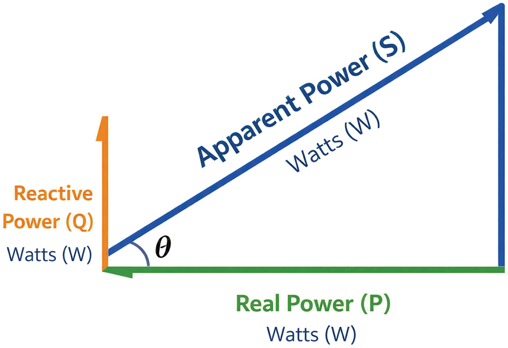
In the case of the inverter, it is taking the real power from the battery and producing both DC power and apparent power, as shown in Figure 5.





The next step in the power mapping is the AC motor; at this point, the inverter has already converted the DC power to AC for the motor. The AC motor is taking in apparent power and converting the power into mechanical power through torque and angular speed.
If the apparent power is used for the input power, the reactive component is used to create the electric/magnetic field. The reactive component is required to generate the real torque.
The other electrical assumption is that the reactive power is used to generate the magnetic/electric field. Without the electric field, the real work could not be accomplished.
The conservation of energy would show the AC power in is equal to mechanical power out, as shown in Equation 9.




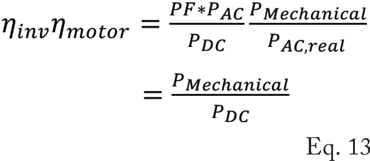
The proposed changes will impact the heat generation of the motor and inverter, and it will impact efficiency.
The other item that needs to be addressed between the mechanical and electrical systems is the mechanical power-to-electrical power relationship at the motor.
The required output power from the motor comes from the mechanical domain. The question now becomes: does the real power from the mechanical domain need to be real power into the motor, or is it a combination of both the real and the reactive powers?
Without reactive power, the motor would not have the magnetic fields required to produce the mechanical work needed.
The main difference between Equation 4 and Equation 11 is the motor efficiency and how it is defined. The apparent power can never be zero, as there will always be either a reactive or real component.
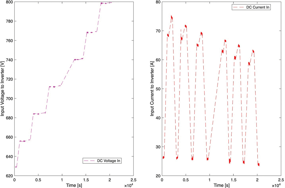
One unusual anomaly found in constant power testing is that the input current to the inverter is dependent on the input voltage; as the input voltage decreases, current increases.
The increase in current will lead to Joule heating and a loss of efficiency. We must understand voltage and current to see how this impacts power transfer.
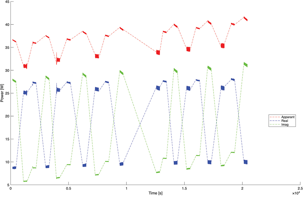
The AC output of the inverter has the real component, a reactive component; the AC power component is shown in Figure 7.
Losses in any system will be seen as light, heat, or sound; in this case, the losses would show up as heat. The next step is to compare the efficiency of the inverter and motor. The comparison of the motor efficiency is shown in Figure 8. The comparison shows the current method of computing efficiency, and the second method is a new efficiency calculation using apparent power.
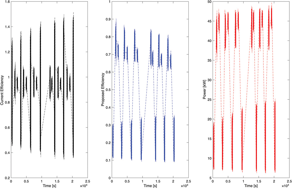
The question that comes up is what component of the apparent power generates the real work being done by the motor. Is it real power from Equation 4 or the apparent power from Equation 11?
If we use only Equation 4, then we neglect the impact of the reactive component. But if we consider Equation 11, we know it is the apparent power. But how much real power do we need and how much reactive power do we need?
This needs to be further analyzed because the mechanical power output is real. So how does this real power transmit to the input power required to the motor? And then we have to ask, how does this power transmit to the output of the inverter?
Our future research will involve the power transfer in the inverter, and the real and reactive power will have to be further examined along with the phase angle. The goal of the inverter research is to obtain an efficiency less than 1 and to better estimate the heat generated from the inverter.

Nicholas Ingarra is a Principal Engineer, technical consultant, and strategic advisor with more than 20 years of experience in advanced energy systems across the automotive, defense, and commercial sectors. He holds a Ph.D. and M.S. in Mechanical Engineering and is a licensed Professional Engineer specializing in electrochemical systems, thermodynamics, and system-level integration. He can be reached at nicholas.ingarra@sbcglobal.net.