EMC concepts explained
Eye Diagram
Part 2: Impact of Driver, HDMI Cable, and Receiver
T

his is the second of two articles devoted to the Eye Diagram. Part 1 presented the fundamental definitions and concepts [1]. This article, Part 2, addresses the impact of driver, HDMI cable, and receiver on signal quality using data eye, based on the following criteria: data eye opening, data mask violation, and data jitter.

Measurement Setup
The study included three different HDMI signal sources, four different HDMI cables, and two different receivers. The block diagram of the measurement setup appears in Figure 1.

The study focused on the evaluation of eye diagrams using the following criteria: eye opening, eye mask violations, and data jitter. The data jitter was presented in the form of a histogram.

Impact of HDMI Sources

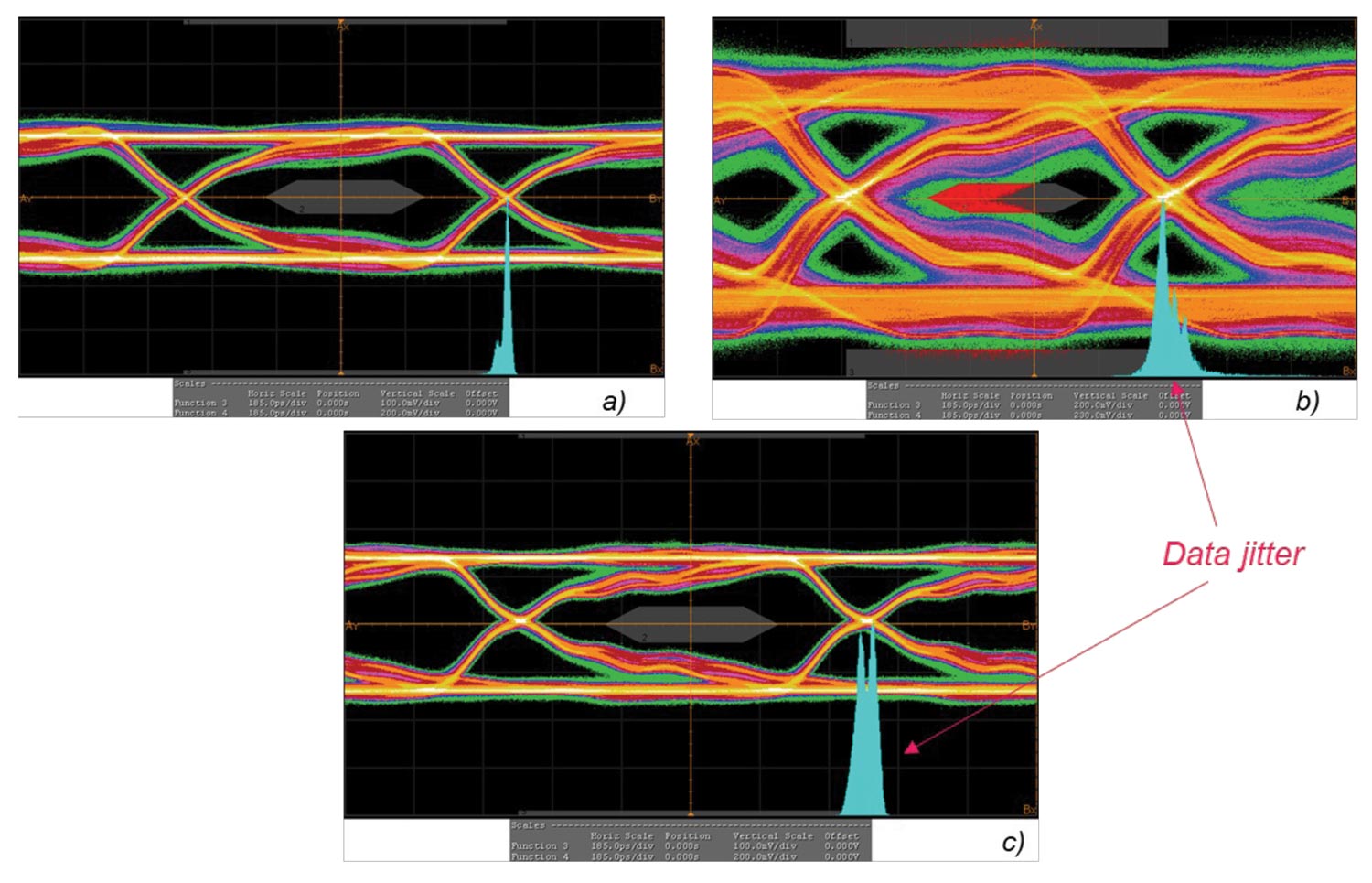
In this part of the study, we compared three different HDMI Sources, while the cable length was the same (3-ft), and the same HDMI Receiver was used (Receiver 1). HDMI Sources used in the study had significant implementation differences. Differences consisted of Driver IC and its configuration, differential trace routing, and HDMI connector style. Figure 2 shows the resulting eye diagrams.
block diagram of the measurement setup
Figure 1: Block diagram of the measurement setup
3-ft cable, same receiver driven by: a) HDMI Source 1, b) HDMI Source 2 c) HDMI Source 3
Figure 2: 3-ft cable, same receiver driven by: a) HDMI Source 1, b) HDMI Source 2 c) HDMI Source 3
Observations: HDMI Source 1 and HDMI Source 3 passed the eye diagram test with a significant margin, while the HDMI Source 2 failed (eye mask violation with large data jitter). Data jitter from HDMI Source 1 was smaller than that from HDMI Source 3.

Next, we evaluated the impact of cable length.

Impact of HDMI Cable Length
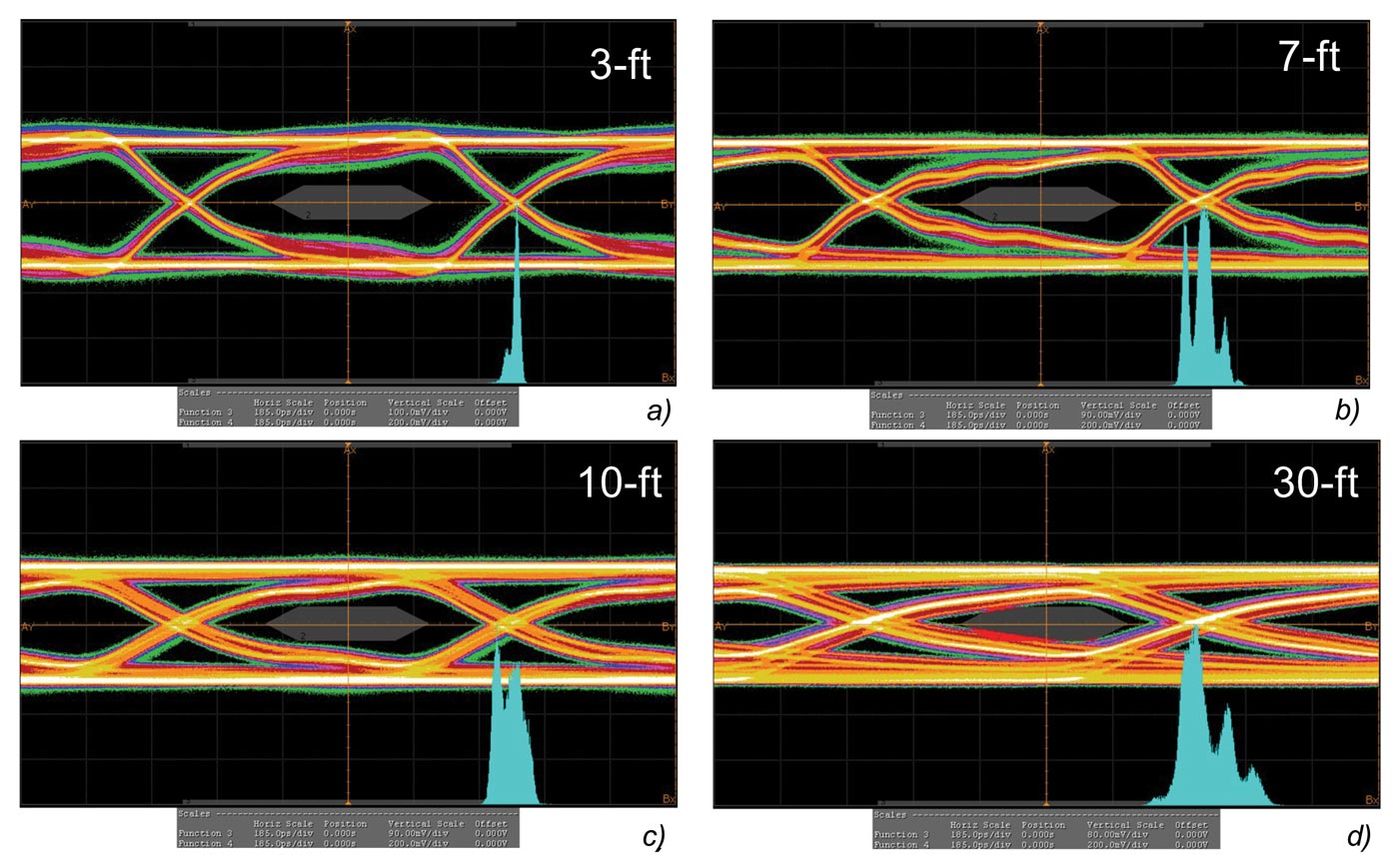
In this part of the study, we evaluated the impact of the cable length with HDMI Source 1 or 2 while keeping the HDMI receiver unchanged. Figure 3 shows the eye diagram for HDMI Source 1 and four different cable lengths.

Observations: HDMI Source 1 passed the test for cable lengths: 3-ft, 7-ft, and 10-ft, but a failure was observed for the 30-ft cable. As the cable length increased, the eye opening became smaller, and the date jitter increased.

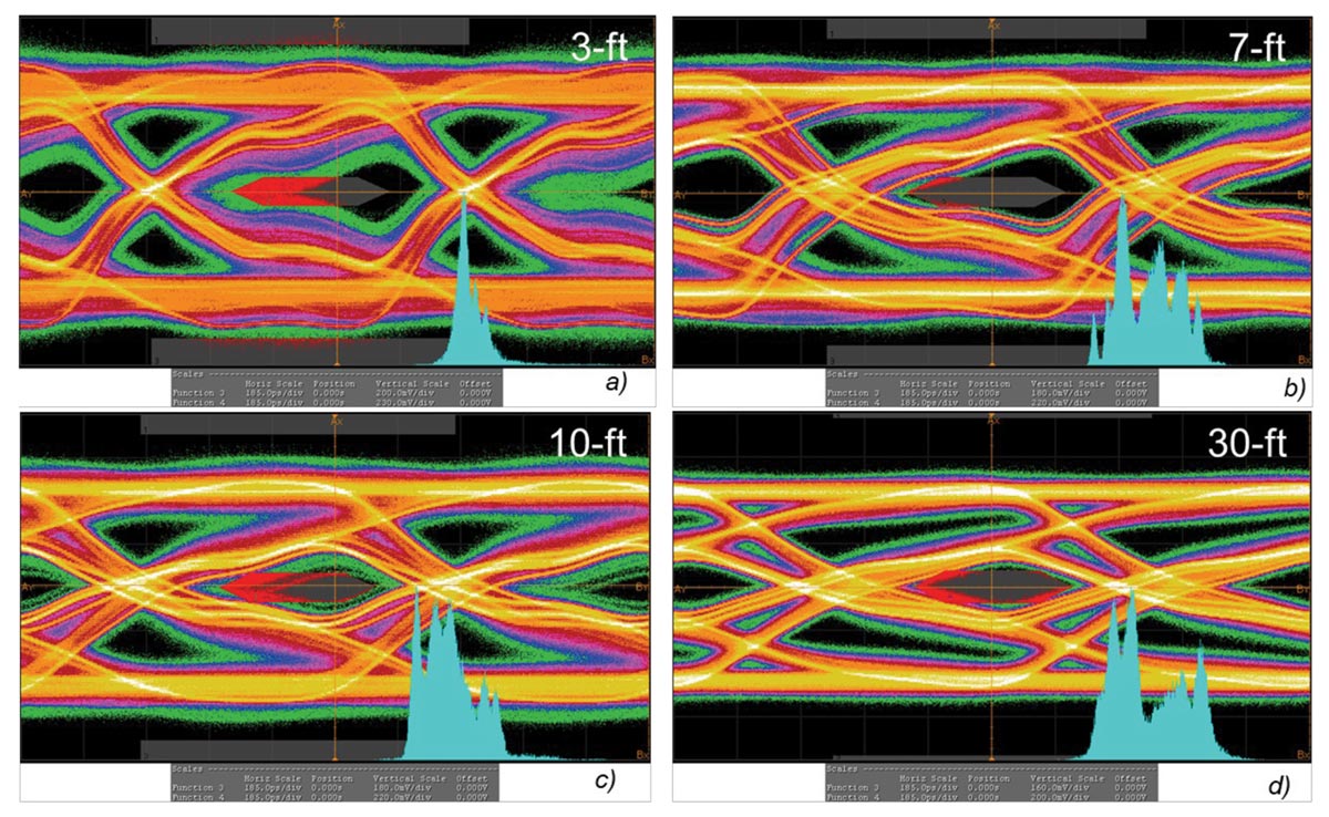
Figure 4 shows the eye diagram for HDMI Source 2 and four different cable lengths.

Observations: The HDMI Source 2 failed the test for all four cable lengths. Generally, as the cable length increased, the eye opening became smaller, and the data jitter became larger.

Impact of HMDI Receiver
In the final stage of the study, we used the same driver, same cable, and two different receivers. Figure 5 shows the corresponding eye diagrams.

Observations: Both receivers passed the test with a similar amount of jitter. The eye opening of the Receiver 1 was slightly larger than that of the Receiver 2.

Impact of cable length driven by HDMI Source 1
Figure 3: Impact of cable length driven by HDMI Source 1
Impact of cable length driven by HDMI Source 2
Figure 4: Impact of cable length driven by HDMI Source 2
Eye diagram: a) HDMI Receiver 1, b) HDMI Receiver 2
Figure 5: Eye diagram: a) HDMI Receiver 1, b) HDMI Receiver 2
Summary and Conclusions

This article addressed the impact of driver, HDMI cable, and receiver on signal quality using data eye, based on the following criteria: data eye opening, data mask violation, and data jitter. The study has shown that all three system components affect the eye diagram. Measurement results have shown a correlation between data jitter and data eye mask opening; as the data jitter increases, the data eye opening gets smaller. The impact of the receiver in our study was less pronounced than the impact of the driver. The most obvious observation was the shorter the cable, the better the data quality.

References
  1. Adamczyk, B., Russa, K., Hare, N., “Eye Diagram – Part 1: Fundamental Concepts,” In Compliance Magazine, August 2022.
Share this story:
Bogdan Adamczyk headshot
Dr. Bogdan Adamczyk is professor and director of the EMC Center at Grand Valley State University (http://www.gvsu.edu/emccenter) where he regularly teaches EMC certificate courses for industry. He is an iNARTE certified EMC Master Design Engineer. Prof. Adamczyk is the author of the textbook “Foundations of Electromagnetic Compatibility with Practical Applications” (Wiley, 2017) and the upcoming textbook “Principles of Electromagnetic Compatibility with Laboratory Exercises” (Wiley 2022). He can be reached at adamczyb@gvsu.edu.
Headshot of Krzysztof Russa
Krzysztof Russa is a Principal Engineer at E3 Compliance LLC. He leads High-Speed design efforts related to Signal and Power Integrity challenges. Years of experience in the design industry with balanced use of simulation and measurement techniques have been recognized by awarding him three times the International Mentor PCB Technology Leadership Award. He can be reached at krzysztof.russa@e3compliance.com.
Headshot of Nicholas Hare
Nicholas Hare is pursuing his Bachelor of Science in Electrical Engineering at Grand Valley State University. He currently works full time as an Electromagnetic Compatibility and Signal Integrity Engineering co-op student at E3 Compliance, which specializes in EMC and high-speed design, pre-compliance, and diagnostics. He can be reached at nicholas.hare@e3compliance.com.