
couple of years ago, I needed to know the shielding effectiveness (SE) of screened cables up to at least 18GHz, but – apart from coaxial cables intended for use in EMC2 test laboratories – I could only find information up to 100MHz, such as Figure 1.
![Effect of varying the length of a shield pigtail termination, from [1]](https://digital.incompliancemag.com/asset/2022/08/ic-sep-22-shielded-fig-2.jpg)
In these measurements, I used many different constructions of cable to try to answer the perennial debate about how best to terminate the individual shields of multiple-shielded cables, including single or double overall braids (overbraids), and individual shielded cables contained within an overbraid.
These measurements covered a great deal more than I have described in this brief article, but I am unable to report the other results for confidentiality and/or security reasons.
But before I can describe the cables and results I am permitted to share with you (see Part 2 of this article), I first need to establish the basic rules for terminating cable shields, so that you understand why I did what I did.
For these cable’s shields to provide the EMC benefits needed, they must be correctly terminated at their ends. Correct termination techniques for RF have been well-proven for decades (see References [1] and [3] through [14], which span the period 1976 to 2019).
Unfortunately, despite all this publicly available knowledge on well-proven shield termination methods, they are still neither well-known nor widely used.
These guidelines were usually acceptable in most ordinary consumer, commercial, and light industrial applications up until the 1990s because their electromagnetic environments were quite benign. But they were never sufficient for applications with very tough electromagnetic environments, as covered by [1] and [3] through [8].
However, when personal/portable computers and digital cellphones became widespread during the 1990s, their large electromagnetic emissions at frequencies up to almost 1GHz meant that IEC and similar EMC test standards for immunity started to test with at least 3 Volts/meter up to at least 1GHz, which is roughly equivalent to a cellphone operating at full power 2 meters away. Such standards were then adopted as part of claiming compliance to the European Union’s EMC Directive.
Even electronic circuits that use low-frequency signals (say, below 20kHz) can be expected to demodulate and intermodulate RF noises (say, above 150kHz), as almost every designer of such products who took the trouble to perform these immunity tests discovered. [3] warned about this issue in the mid-1990s.
Now, in the 2020s, we can look back on thirty years of ever-worsening electromagnetic environments, and the EMC test standards for ordinary consumer, commercial, and light industrial applications now have to test immunity up to 6GHz or more. 28GHz will soon be necessary when 5G is extended into that frequency range as planned, see [15] and [16].
These days, the plain fact of the matter is that all analog and digital signals, and all power, are now heavily polluted with conducted RF noises up to at least 6GHz. These are common mode (CM) noises that are both picked up from the noisy electromagnetic environment, and created by the electronics themselves, even being emitted from analog inputs! (See [17].)
The result is that all guidelines for shielding low-frequency signals and power are now insufficient for EMC compliance, and techniques for shielding against high-frequency RF noises are always required, including instances when using RF filtering [18]. Reference [12] and all the other references in this article describe such techniques, and they all require terminating cable shields in 360°, and at both ends.
Based on my own experience and that of the many EMC experts I know worldwide, the good news is that doing this not only results in good EMC, but also the quickest and most cost-effective project designs, and the quickest and most cost-effective installations (see [19]).
There is also some persuasive real-world evidence for improvements in functional performance where legacy equipment and its installations have been redesigned to use shielded cables terminated in 360° at both ends (see the two examples in [20]).
It is sometimes also referred to as all-around, circumferential, or peripheral termination.
And shield termination is sometimes called shield bonding, shield grounding, or shield earthing. However, I strongly advise against using terms based on ground or earth for anything other than electrical safety purposes (see [21]).
As for worries about so-called ground loops, hum loops, earth loops, etc., when bonding cable shields at both ends, see my blog [22] and remember that bonding cable shields at both ends has been a requirement for military electronics since 1976 (see [3] through [11]).
We can always deal with such noisy loops by circuit design, which I learned how to do in the 1980s. Without such circuit design, the only generic alternative for poor EMC caused by badly shielded cables is to use shielded panel-mounted filters and/or better cable shielding. Of the two, better cable shielding is quicker and more cost-effective unless we are stuck with legacy cable systems that can’t be replaced.
Note that fiber-optic converters and their cables may seem costly but can be more cost-effective overall, taking everything into account. I expect them to become more economically favorable year-on-year, going forward.
All the references at the end of this article warn against using pigtails, sometimes simply called tails.
Figure 2 shows that even a 5mm pigtail makes shielding worse than 360° termination by between 10 and 20dB over the range 1MHz to 1GHz. Note that manual pigtailing is very difficult indeed if shorter than 20mm, which Figure 2 shows is up to 30dB worse.
![Effect of varying the length of a shield pigtail termination, from [1]](https://digital.incompliancemag.com/asset/2022/08/ic-sep-22-shielded-fig-3.jpg)
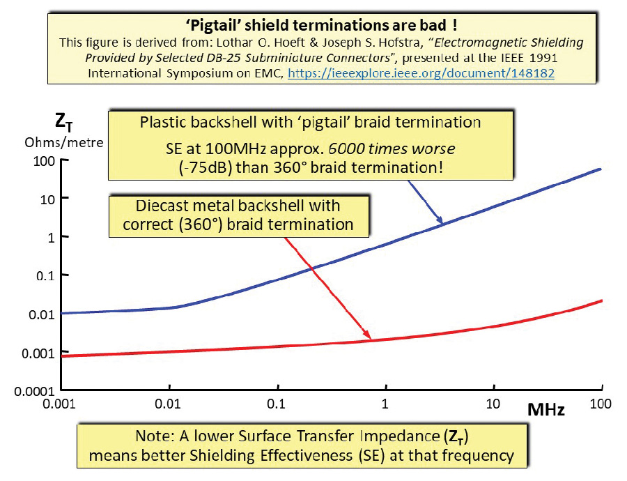
However, the shielding degradation caused by using pigtails instead of 360° terminations depends very much on the test method used. For example, a 1991 study [23] found that using a pigtail in a subminiature 25-way D-type made shielding 20dB worse at 1kHz (only 1kHz!) and 75dB worse at 100MHz (see Figure 3).
If, in ten years’ time, you remember only two points about this article they should be:
- Never use pigtails for terminating cable shields; and,
- Always terminate shields at both ends (dealing with the inevitable ground loops, hum loops, etc., by circuit design, see [22]),
By remembering these two key points, you will almost certainly have saved yourself a great deal of work, cost, and project delays by reducing the number of design iterations required to pass EMC tests. (It is usually practical to design to quickly and cost-effectively design to pass EMC tests the first time, see [19] and [20].)
For a simple method for predicting a cable’s SE from measurements of ZT (surface transfer impedance, as used in Figure 3), see [24].
As their EMC specifications were required by their customers to be the toughest of all the UK’s Defense Standards, these cables or cable bundles were all shielded with two layers of overbraid, directly in contact with each other along their lengths, as recommended by [1].
Many of the cables or cable bundles contained internal braid-shielded twisted-pair (TP) or multicore cables, with their individual braids insulated from the whole cables’ or cable bundles’ overbraids by their individual plastic jackets.
The customers for these equipment designs had made several of their own proprietary specifications for EMC design, assembly, and installation part of the contract for supply. Unfortunately, their own specifications did not always agree with each other, or with [1] when it came to issues of how to deal with the individual shields and overbraids of the cables or cable bundles.
Each designer of the suppliers’ equipment cables or cable bundles seemed to have been differently confused by their customers’ inconsistent shielding requirements, with the result that different cable assembly drawings often differed from each other in their use of shield termination methods. Some cable assembly drawings even contained an eclectic mix of shield-terminating methods because they had been worked on by different designers at different times.
Enquiring as to why this was the case, I discovered that no designers at either supplier even knew about the existence of the official UK guidance on terminating shields in [1], despite compliance with [1] also being part of their contract requirements. This was even the situation with one supplier whose designers I had trained in good EMC design/assembly techniques three years beforehand. They relied almost entirely on subcontract designers, and in the intervening three years, these had all been replaced by new subcontractors who had not attended my course!
As well as the usual issues of which ends of the shields, or both, to terminate, whether pigtails could be used, and whether to connect internal cable shields to the overbraids or not, there was also the issue of whether to insert a thin insulating tube in between two overbraids.
Many of the cable bundles were 2 inches or more in diameter and, when assembled with two overbraids in direct contact with each other along their lengths, very stiff, making them difficult to install in military vehicles. Adding an insulating tube between their overbraids made them usefully more flexible, but I knew (from [3], [4], [1], and other reference materials) that this should reduce their shielding effectiveness (SE).
Some customers’ specifications required thin insulating layers between double overbraids without commenting on the likely impact on EMC. This might have been because they wanted the mechanical flexibility and didn’t realize that SE could be compromised. But it could also have been because they had seen some of the few references listed below (but not [1], [3], [4], [9], or [10]) that claim (incorrectly, in my view) that placing an insulating film between two overbraids along their length gives a 10 to 30dB improvement in SE, compared with two overbraids in direct contact along their length.

So, I wanted to discover for myself, and for the benefit of other designers on these projects, how best to design and assemble the shields in their cables or cable bundles, and above what frequency we might need to have to use filtering or galvanic isolation techniques (such as fiber-optics) because flexible metal shielding layers would be no use anymore.
- Ministry of Defence (UK), Defence Standard 59-411 Part 5, Issue 3, 14 June 2019, “Electromagnetic Compatibility – Part 5 : Code of Practice for Tri-Service Design and Installation.”
- All conductors (including any metalwork) are accidental antennas (whether we want them to be or not!). See https://www.emcstandards.co.uk/the-physical-basis-of-emc and/or the webinars available at https://www.emcstandards.co.uk/understanding-emc-basics-a-3-part-series.
- Ministry of Defence (UK), Defence Standard 59-41 (Part 7)/Issue 1, 10 November 1995, “Electromagnetic Compatibility – Part 7: Code of Practice for HM Ships – Installation Guidelines.”
- Ministry of Defence, Defence Standard 59-41 (Part 6)/Issue 1, 26 August 1994, “Electromagnetic Compatibility – Part 6: Code of Practice for Military Vehicles – Installation Guidelines.”
- SSP 30242 Revision E, NASA, “Space Station Cable/Wire Design and Control Requirements for Electromagnetic Compatibility – International Space Station,” Revision E, 22 December 1998.
- MIL-HDBK-1857, 27 March 1998, “Department of Defense – Handbook – Grounding, Bonding, and Shielding Design Practices.” This is an unchanged re-issue of MIL-STD-1857 (EL), dated 30 June 1976.
- MIL-STD-1310G (Navy), 28 June 1996, “Department of Defense – Standard Practice for Shipboard Bonding, Grounding, and Other Techniques for Electromagnetic Compatibility and Safety.”
- NAVAIR AD 1115, “Electromagnetic Compatibility Design Guide for Avionics and Related Ground Support Equipment,” 3rd Edition June 1988.
- IEC 61000-5-2:1997, “Electromagnetic Compatibility (EMC) – Part 5: Installation and mitigation guidelines – Section 2: Earthing and cabling,” from the BSI and IEC web shops.
- “EMC for Systems and Installations,” Tim Williams and Keith Armstrong, Newnes 2000, 0-7506-4167-3, https://www.emcstandards.co.uk/emc-for-systems-and-installations2.
- Patrick G. Andre and Kenneth Wyatt, EMI Troubleshooting Cookbook for Product Designers, Scitech Publishing, 2014, ISBNs: 978-1-61353-019-1 (hardback) 978-1-61353-041- 2 (PDF), see subsections 4.8.1 and 6.8.
- Henry W. Ott, Noise Reduction Techniques in Electronic Systems, Second Edition, 1988, Wiley Interscience, ISBN 0-471-85068-3.
- William G. Duff, Designing Electronic Systems for EMC, Scitech Publishing, 2011, ISBN: 978-1- 891121-42-5.
- Elya B. Joffe and Kai-Sang Lock, Grounds for Grounding, Wiley, IEEE Press, ISBN: 978-0471- 66008-8.
- “Unleash the Full 5G Potential with mmWave,” https://www.qualcomm.com/research/5g/5g-nr/mmwave.
- “Fact Sheet: Spectrum Frontiers Rules Identify, Open Up Vast Amounts of New High-Band Spectrum for Next Generation (5g) Wireless Broadband,” https://docs.fcc.gov/public/attachments/DOC-340310A1.pdf.
- “There are no low-frequency systems any more!” https://www.emcstandards.co.uk/there-are-no-low-frequency-systems-any-more. Also relevant: https://www.emcstandards.co.uk/ground-power-bounce-cause-noise-emissions-from.
- “Shielding and Filtering Don’t Work Independently of Each Other,” https://www.emcstandards.co.uk/shielding-and-filtering-don-t-work-independen. Also relevant: https://www.emcstandards.co.uk/skin-effect-and-surface-currents1.
- “SavingtimeandmoneywithgoodEMCdesign,” https://www.emcstandards.co.uk/saving-time-and- money-with-good-emc-design2.
- https://www.emcstandards.co.uk/testimonials-2014
https://www.emcstandards.co.uk/testimonials-2017 - “What’sinaname?” https://www.emcstandards.co.uk/what-s-in-a-name.
- “Earth Loops, Ground Loops, and Hum Loops,” https://www.emcstandards.co.uk/earth-loops-ground-loops-and-hum-loops.
- Lothar O. Hoeft and Joseph S. Hofstra, “Electromagnetic Shielding Provided by Selected DB-25 Subminiature Connectors,” IEEE 1991 International Symposium on EMC, August 12- 16, 1991, Cherry Hill, NJ., ISBN: 0-7803-0158-7, https://ieeexplore.ieee.org/document/148182
- Michel Mardiguian, “Simple Method for Predicting a Cable Shielding Factor, Based on Transfer Impedance,” Interference Technology Magazine, EMC Directory & Design Guide 2012, http://www.interferencetechnology.com/wp-content/uploads/2012/03/Mardiguian_DDG12.pdf.
- Cherry Clough Consultants’ EMC Training Course, Module 2, EMC in Cable Interconnections; course notes, https://www.emcstandards.co.uk/2-emc-in-interconnections-techniques-for-cables.