s a product designer, one of the biggest issues you’ll face is radiated emissions. This month, we’ll describe the minimal set of tools to characterize and help mitigate radiated emissions right on your workbench.
These can either be constructed as DIY projects or commercial probe kits may be purchased. Flexible or semi-rigid coaxial cables may be used. H-field (loop) probes may be constructed by soldering the center conductor to the shield, as in Figure 1. An E-field probe may be constructed by cutting away a short (5mm) portion of the shield, exposing the center conductor. Both types of DIY probes should be dipped in rubberized “tool dip” or otherwise insulated to avoid shorting out circuitry. See the example in red.

Let’s start off with the most basic probe; E-field (voltage measurement) and H-field probes (current measurement). These are designed to be most sensitive to either E-fields or H-fields, respectively.
H-field probes are most sensitive to currents in wires or cables. While these DIY versions have an unbalanced geometry, which creates common mode currents flowing up the “handle” portion, they are still useful for general troubleshooting.
E-field probes are more sensitive to components that create large E-fields, such as heat sinks and any circuit switching large voltages. A good example of large changing voltages would be off-line switching power converters.
The advantage to commercial near field probes is that they are insulated and, being longer and thinner, can penetrate into narrow spaces (Figure 2). Commercial probes come as sets, usually three H-field probes in different sizes and an E-field probe. Beehive Electronics and Tekbox probe sets are about $350. Make sure to order the cable (sold separately) for the Beehive probes.

Near field probes are most useful for identifying major energy sources on PC boards and internal cables. I use H-field probes for detecting high currents (as in ICs and circuit traces) and E-field probes for detecting high voltage swings (as in buck converters). A record of the harmonic spectrum for each major energy source should be recorded.
By measuring and monitoring these RF currents, we can often perform troubleshooting right on our workbenches and mitigate emissions prior to taking the product to the compliance test lab. Reducing these RF currents will also reduce the cable emissions.
While I personally own several commercial current probes, those pictured in Figure 3 are the ones I started out with for a couple of years before I could afford a good set. Many of my clients are helped remotely, and I’ve had them make these DIY probes so I can guide their troubleshooting efforts.

The fact these DIY probes are uncalibrated is unimportant when used for troubleshooting purposes since we’re only looking for relative changes. For example, if we know we’re failing by 5 dB, then at the workbench, we’ll want to apply mitigations to reduce the harmonic amplitude by 10 to 15 dB for safety.
Eventually, you’ll want to purchase a calibrated RF current probe. Figure 4 shows an affordable commercial probe from Com‑Power. Similar affordable probes are available from Tekbox. Be sure to order one that can clamp around the wire or cable to be tested.

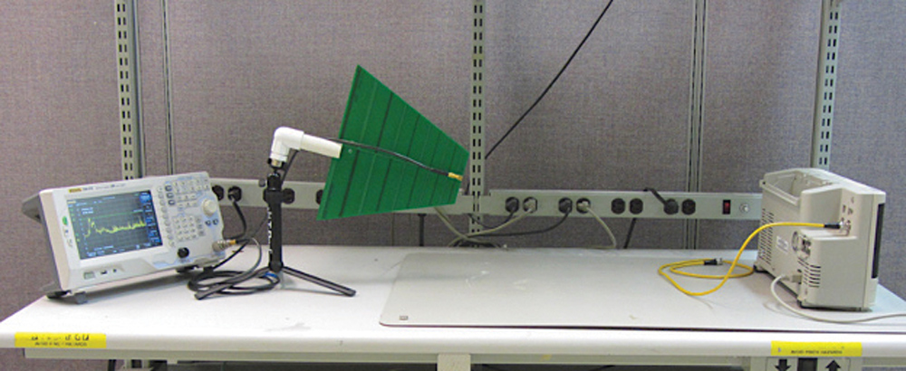
The antenna I like to use is made by Kent Electronics and costs just $38. I show how to make the PVC fixture that attaches to a table-top tripod in Reference 2.
There are several other good choices in analyzers, and Rigol and Siglent have captured much of the affordables market. Many other alternatives are described in Reference 1. The U.S. distributor for these models is Saelig Electronics.
- Wyatt, Create Your Own EMC Troubleshooting Kit (Volume 1, 2nd Edition), Amazon, 2022
- Wyatt, “PC Board Log Periodic Antennas,” EDN.