EMC concepts explained
Impact of PCB Via and Trace Geometry on the Effectiveness of Decoupling Capacitors
Part 1: Board Topologies and the PCB Circuitry
T

his is the first of several columns investigating the effectiveness of decoupling capacitors while varying the topology of vias, trace length between the decoupling capacitor and the integrated circuit (IC) power/ground pins, and distance from the internal power and ground plane pair. Specifically, the impact of the PCB geometry will be evaluated by performing RF Emission testing on six PCB variants, according to the CISPR 25 standard. Part 1 of this study defines the board topologies and the PCB circuitry. The following parts will show the RF Emissions results.

Schematic of the PCB Circuitry
Figure 1 shows the circuit schematic. The PIC10F200 microcontroller [1] was programmed to blink three LEDs using PWM [2]. To keep the current of each I/O pin below the allowable maximum of 25 mA rating, each LED was wired in series with a resistance of 116 Ω. Fourteen 0402 capacitor pads were grouped in two blocks of seven, as shown in Figure 2.
Figure 1: Circuit schematic
Figure 2: Block of the capacitor pads
One block (C1 – C7) of pads was on the top layer, while the other (C8 – C14) was on the bottom layer. The first pad in each block was 0.1 inch away from the PWR and GND pins of the IC, while the remaining six pads were placed at 0.5-inch distance increments. Only one pad at a time was populated with a 0.1 µF X7R capacitor, [3].
Via and Trace Topologies
Six PCBs were designed incorporating the capacitor placements explained above, but each variant had a different via topology, as shown in Figure 3.
Figure 3: Different via topologies for each PCB
Board A had four vias connected to the capacitor. Two vias led to the board’s internal power plane and were placed on either side of the capacitor’s power pin, approximately 0.03 inches away from the center of the pin pad. The other two led to the board’s internal ground plane and were placed on either side of the capacitor’s ground pin at the same distance. 0.03 inches separated each power and ground via pair. Straight traces connected the vias to the capacitor.

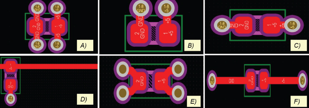
Board B was similar to Board A but had only two vias connected to the capacitor instead of four. The via leading to the internal power plane was placed 0.03 inches above the capacitor’s power pin, while the via leading to the internal ground plane was placed 0.03 inches above the capacitor’s ground pin. Again, there was 0.03 inches of separation between the power via and the ground via.

Board C had two vias connected to the capacitor, where one was approximately 0.026 inches to the left of the capacitor’s ground pin, and the other was 0.025 inches to the right of the capacitor’s power pin. 0.085 inches separated the vias from each other.

Small changes in a PCB layout can make or break decoupling capacitor performance. This study compares six different via topologies—from single-via designs to four-via configurations—to see which approaches reduce RF emissions and which fall short.
Board D used only one via, which connected to the board’s internal ground plane and was placed approximately 0.026 inches away from the center of the capacitor’s ground pin. A long trace ran from the capacitor’s power pin to the PIC10F200’s power pin.

Board E had four vias connected to the capacitor. Each via was placed at a vertical distance of approximately 0.015 inches and a horizontal distance of approximately 0.026 inches from the center of the respective capacitor pin. This left 0.086 inches of distance between each power and ground via pair. The traces connecting the vias to the capacitor pin pads were also curved.

Board F was similar to Board C but had a longer trace between each via and the capacitor. Each via was approximately 0.1 inches from the center of its respective capacitor pin pad, making the distance between the vias 0.234 inches.

PCB Topology
In our study, we used a six-layer PCB [4] with the topology shown in Figure 4.
Figure 4: Topology of the 6-layer PCB
1 oz Cu was used for the outer layers, while ½ oz Cu was used for the inner layers. Closely-spaced power and ground plane pair is closer to the top layer than the bottom layer. This impacts the current loop area and thus the loop inductance during switching.
Ground planes had no pullback distance from the board edges, while the power plane was pulled back a distance of 20H, with H being the thickness of the core.
Future Work
The next article in the series will discuss the measurement setup and the test results of the conducted emissions according to CISPR 25 regulations.
References
Share this story:
Bogdan Adamczyk headshot
Dr. Bogdan Adamczyk is professor and director of the EMC Center at Grand Valley State University (http://www.gvsu.edu/emccenter) where he performs EMC educational research and regularly teaches EM/EMC courses and EMC certificate courses for industry. He is an iNARTE-certified EMC Master Design Engineer. He is the author of two textbooks, “Foundations of Electromagnetic Compatibility with Practical Applications” (Wiley, 2017) and “Principles of Electromagnetic Compatibility: Laboratory Exercises and Lectures” (Wiley, 2024). He has been writing “EMC Concepts Explained” monthly since January 2017. He can be reached at adamczyb@gvsu.edu.
Allyson Telck headshot
Allyson Telck is participating in a combined degree program to earn a Bachelor of Science in Electrical Engineering and a Master of Science in Biomedical Engineering at Grand Valley State University. She recently completed her final rotation as an Electromagnetic Compatibility Engineering co-op student at E3 Compliance, which specializes in EMC and high-speed design, pre-compliance testing, and diagnostics. She can be reached at allyson.telck@e3compliance.com.
Scott Mee headshot
Scott Mee is a co-founder and owner at E3 Compliance, which specializes in EMC & SIPI design, simulation, pre-compliance testing, and diagnostics. He has published and presented numerous articles and papers on EMC. He is an iNARTE certified EMC Engineer and Master EMC Design Engineer. Mee participates in the industrial collaboration with GVSU at the EMC Center. He can be reached at scott.mee@e3compliance.com.