any of my clients are power electronics companies that specialize in making switched-mode power supplies and motor drives. During the conducted emission tests, one of the challenges these manufacturers face is the resonance peaks in the harmonic noise somewhere between 10 MHz and 30 MHz. Often, no amount of filtering will eradicate or attenuate the peak. This is so typical that it is worth investigating the root causes of these peaks.
When the circuit is energized with multiple energy sources (hard-switching devices in the circuit), it will show the resonance peak in the test results. As in the 10s of MHz frequency range, it is the rise time of the switching event that determines the energy level. It is safe to conclude that the resonance peak is caused by how hard the switching event is (rise time) rather than how often it is switched (frequency).
It is also worth mentioning that in 10s of MHz, the conducted emission of a switched-mode power supply is predominantly common mode.
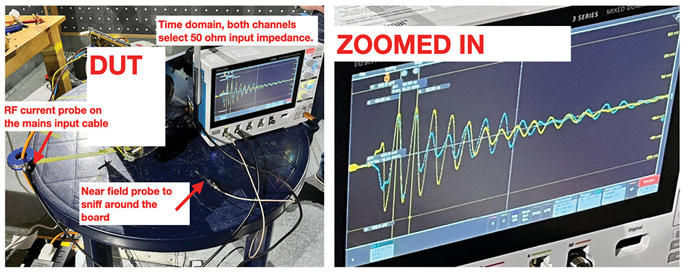
To locate the noise source, it is essential to understand the relationship between the time domain and the frequency domain. A resonance peak observed in the frequency domain can also be observed in the time domain. Wyatt provides a demonstration of this concept in a video [2].
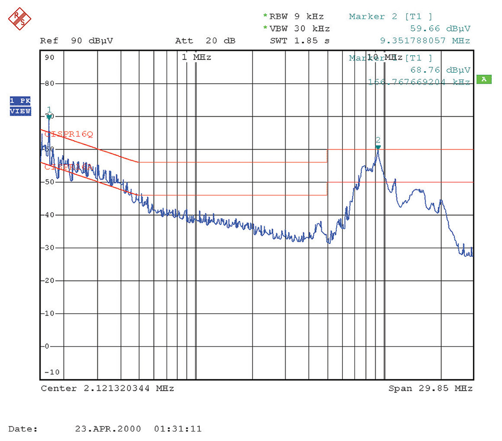
Figure 2 illustrates the setup for locating the noise source. An RF current probe is positioned on the mains cable and connected to the 50-ohm input of an oscilloscope (channel 2 in this case). Channel 1 of the oscilloscope (also configured to be a 50-ohm input) is connected to a near-field probe. The measurement result from the RF current probe serves as a stable trigger. By moving the near-field probe to accessible parts of the system, we can compare the noise signal picked up by the near-field probe with the RF current probe signal. The noise signal picked up by the near-field probe can be in phase or anti-phase compared with the RF probe.
Once the noise source is identified, we can proceed to develop strategies for mitigating its impact. In this case, the solution involves optimizing the RC snubber circuit of the PFC circuit, which utilizes a SiC MOSFET. The high noise level experienced can be attributed to the SiC MOSFET. By implementing improvements to the RC snubber circuit, we can effectively reduce the noise generated by the PFC circuit.
- T. Williams, EMC for Product Designers, Fifth edition, Newnes, 2017.
- K. Wyatt, “Switch-Mode Power Supply – Ringing Demo.” https://youtu.be/dHDAuxRcReo
- D. C. Smith, High Frequency Measurements and Noise in Electric Circuits, Springer, 1992.

Dr. Min Zhang is the founder and principal EMC consultant of Mach One Design Ltd, a UK-based engineering firm that specializes in EMC consulting, troubleshooting, and training. His in-depth knowledge in power electronics, digital electronics, electric machines, and product design has benefitted companies worldwide. Zhang can be reached at info@mach1desgin.co.uk.