In Compliance: The Compliance Information Resource for Electrical Engineers logo
Pre-Compliance
EMI Testing
Passing Compliance Test the First Time
PLUS
(Re)Discovering the Lost Science of Near-Field Measurements, Part 2

Clock Duty Cycle Tuning for Desense Mitigation in Modulation‑Involved Cases

The Legal Perils of Customer Service

PLUS
(Re)Discovering the Lost Science of Near-Field Measurements, Part 2

Clock Duty Cycle Tuning for Desense Mitigation in Modulation‑Involved Cases

The Legal Perils of Customer Service

August 2023
AR
This is How You Reduce
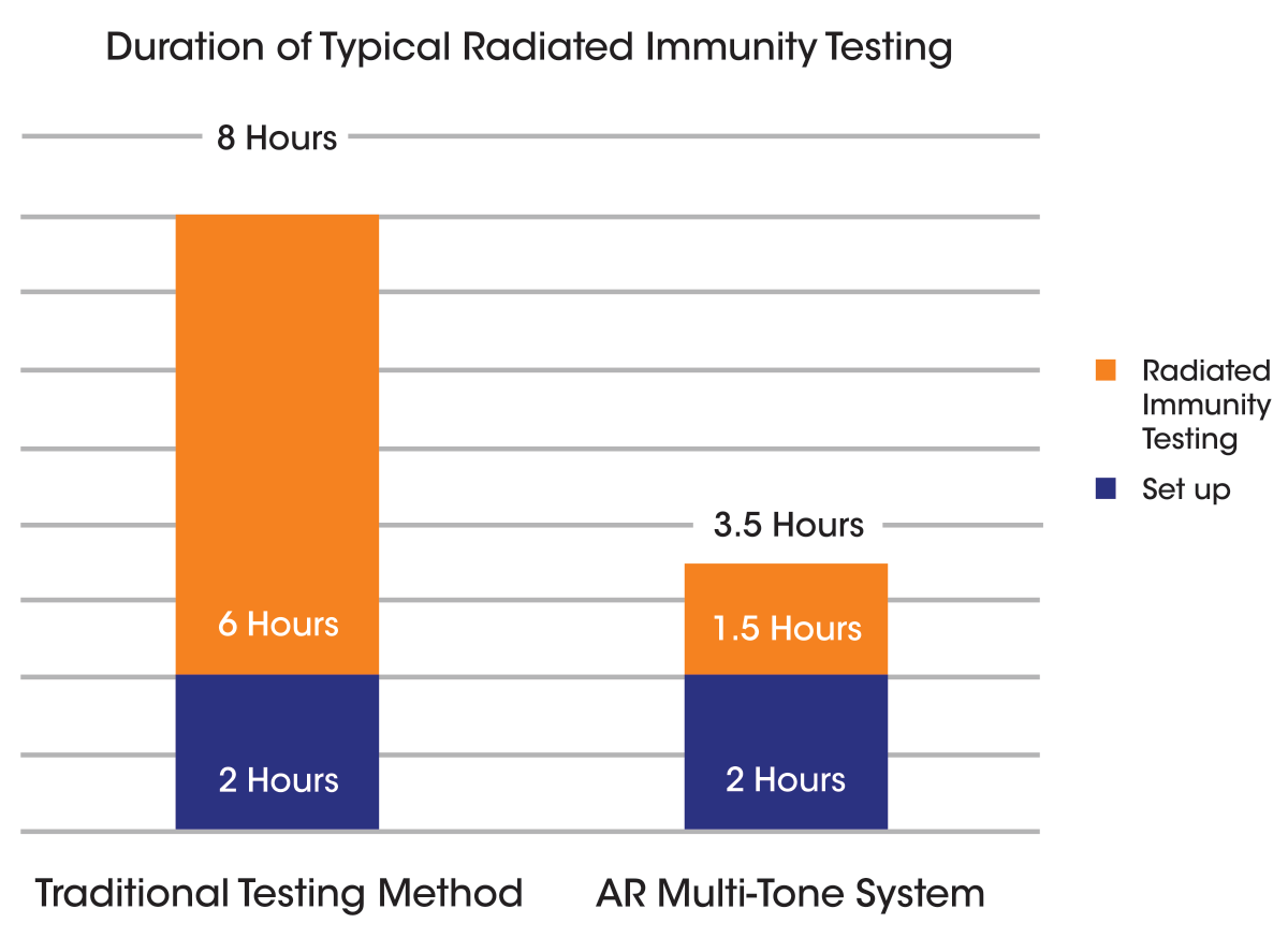
Testing Time by More Than 50%
With regulatory adoption of multiple signal radiated immunity test methods (IEC-61000-4-3:2020, 4th edition), AR’s Multi-Tone System enables you to vastly reduce your test times in accordance with automotive, commercial, and aviation EMC RI standards. Included is AR’s proprietary emcware® software, offering users numerous test and calibration routines utilizing multiple signal methodology, to meet these standards.

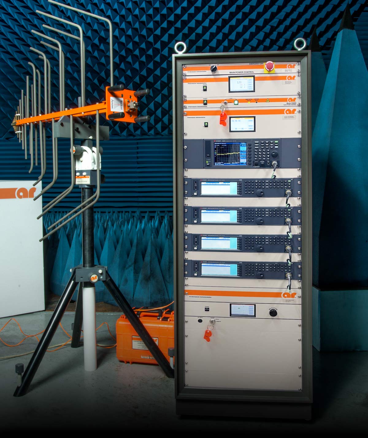
For example, AR’s Multi-Tone System can reduce the typical time to run traditional tests such as IEC 61000-4-3, ISO 11451, and ISO 11452, by over 50%. In the event of an EUT failure, margin investigation and traditional single tone testing is easily performed through AR’s emcware® software.

Graph
Multiple full sweeps are often required during mitigation efforts, which is where the multiple signal approach will pay dividends.

This is a creative way to help your company be more profitable by using your assets more efficiently.

Visit us at www.arworld.us or call 215-723-8181.
Talk to an applications engineer at 800.933.8181.
AR logo
AR logo
AR logo
We’re with you all the way
ar rf/microwave instrumentation - ar modular rf - sunar - ar europe
In Compliance logo
In Compliance Magazine
ISSN 1948-8254 (print)
ISSN 1948-8262 (online)
is published by

Same Page Publishing Inc.
451 King Street, #458
Littleton, MA 01460
tel: (978) 486-4684
fax: (978) 486-4691

©Copyright 2023 Same Page Publishing, Inc. all rights reserved

Contents may not be reproduced in any form without the prior consent of the publisher.
While every attempt is made to provide accurate information, neither the publisher nor the authors accept any liability for errors or omissions.

editor/
publisher
Lorie Nichols
lorie.nichols@incompliancemag.com
(978) 873-7777

business development director
Sharon Smith
sharon.smith@incompliancemag.com
(978) 873-7722

production director
Erin C. Feeney
erin.feeney@incompliancemag.com
(978) 873-7756

marketing director
Ashleigh O’Connor
ashleigh.oconnor@incompliancemag.com
(978) 873-7788

circulation director
Alexis Evangelous
alexis.evangelous@incompliancemag.com
(978) 486-4684

features editor
William von Achen
bill.vonachen@incompliancemag.com
(978) 486-4684

senior contributors
Bruce Archambeault
bruce@brucearch.com
Leonard Eisner
Leo@EisnerSafety.com
Daryl Gerke
dgerke@emiguru.com

columns contributors
EMC Concepts Explained
Bogdan Adamczyk
adamczyb@gvsu.edu
Troubleshooting EMI Like a Pro
Min Zhang
info@mach1desgin.co.uk

Hot Topics in ESD
EOS/ESD Association, Inc
info@esda.org

advertising
For information about advertising contact Sharon Smith at sharon.smith@incompliancemag.com.

subscriptions
In Compliance Magazine subscriptions are free to qualified subscribers in North America.
Subscriptions outside North America are $129 for 12 issues. The digital edition is free.
Please contact our circulation department at circulation@incompliancemag.com

August 2023
Volume 15 l Number 8
Contents
By Paul Denisowski
Pre-compliance testing saves time and costs by detecting potential problems early in the design process. The use of appropriate tools and techniques improves the chances of passing the full compliance test on the first try.
By Ken Javor
This article is the third in a series commemorating 70 years since the advent of modern EMI testing. But this last article is itself divided into multiple parts, due to the topic’s complexity. Unlike the previous two articles, which mainly tracked evolution and explained issues, this series of installments argues that we started off correctly seventy years ago, but then took the wrong fork in the road in 1967.
By Shengxuan Xia, Jun Fan, and Chulsoon Hwang
This paper provides a comprehensive study on how to mitigate desense with the change in the spectrum distribution by tuning the duty cycle of the interfering clock. Measurements conducted on a real cellphone showed a 10 dB suppression of desense for certain TX bandwidth condition.
By Kenneth Ross
Customer service, before and after sale, is one of the most important functions that must be performed by a manufacturer or product seller. It is also one of the riskiest. Obtaining no information, inadequate information, wrong information, misleading information, or harmful information can make it difficult to evaluate future risk, meet your regulatory obligations, and defend a product liability lawsuit.
wooden blocked being turned to say "Passed" instead of "Failed"
person hunched over using a lantern in a dark empty space
a cell phone with half of it showing the insides
several different light bulbs that have words spelled out on the inside
compliance news
U.S. House Proposes Removal of Private Use Land Restrictions for Amateur Radio
Members of the U.S. House of Representatives have reintroduced legislation that would remove certain private land use restrictions that apply to the installation or use of amateur radio antennas.

According to a posting on the ARRL website, the legislation, H.R. 4006, also known as the “Amateur Radio Emergency Preparedness Act,” is intended to support the ability of amateur radio operators to install “reasonable” antennas and antenna structures on property or land that they own or control…

New Thermal Management Process Could Double Life-Span of EV Batteries
An Israeli company is pioneering the development and use of a battery system for electric vehicles (EVs) that can offer both increased safety and extended battery life.

According to a posting on the yahoo!finance website, the company, Carrar, has developed a two-phase battery thermal management solution that minimizes the risk of thermal runaway, thereby significantly increasing battery safety. At the same time, by optimizing the operating temperature range of the battery…

Feature Article
Pre-Compliance EMI Testing
Passing Compliance Tests the First Time
By Paul Denisowski
letter wooden blocks changing from failed to passed
M

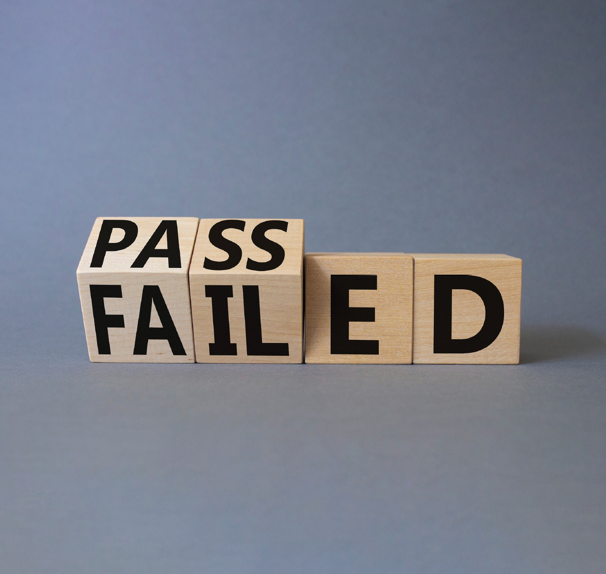
ost electrical and electronic devices must be tested by third-party labs to ensure that they comply with the relevant conducted and radiated emissions standards. The failure rate in compliance tests is often high, requiring costly and time-consuming redesign. With pre-compliance testing of electromagnetic interference (EMI) as part of the design process, manufacturers can identify problems early in the product cycle. Pre-compliance testing makes it easier to modify the design and electromagnetic properties of a product and increases the probability of passing compliance tests the first time.

Devices must be tested to show that they comply with the requirements of various standards, such as CISPR or MIL-STD. These standards are specified by the responsible regulatory authority, such as the Commission of the European Union (EU) or the Federal Communications Commission (FCC) in the U.S. The required compliance tests must be passed before a device can be put on the market.

Feature Article
(Re)Discovering the Lost Science of Near-Field Measurements, Part 2
Understanding Radiated Emissions Measurements Made at One-Meter Separation: It’s Not What You’ve Been Led to Believe
By Ken Javor
Drawing of man illuminating a dark room with a lantern
T

his is the second part of our article “(Re)Discovering the Lost Science of Near Field Measurements.” Part 1 of the article (see In Compliance Magazine, July 2023) explained what near and far field measurements entail, and that one-meter measurements are very much near field. This second part picks up where Part 1 left off, and explains the evolution of the earlier 12” and present-day one-meter separation measurements, considerations in antenna selection, and the difference between antenna-induced and field strength limits, and the evolution from one to the other.

Near and Far Field Limit Derivation
It is instructive to compare and contrast how the limits in standards such as CISPR 22/32 were determined, vs. those in MIL-I-6181. Limit derivation for standards like CISPR 22/32 comes directly from specifications on the quality of radio services.14

Exodus

Above
the Rest
…providing
industry firsts
with our frequency
& power capabilities
three quarter view of the AMP4066A-1LC, 26,5-40GHz, 100W
AMP4066A-1LC, 26.5-40GHz, 100W
Exodus provides “Industry Firsts” covering these frequency ranges in all SSPA:

1.0-18.0GHz, 100W, 200W, 300W, 500W…
1.0-40.0GHz, as well and for the 18.0-40.0GHz range 40W, 100W, 200W

No other company
can do this anywhere!!!
Exodus Advanced Communications logo
3674 E. Sunset Road, Suite 100, Las Vegas, Nevada 89120
702-534-6564 • www.exoduscomm.comsales@exoduscomm.com
Feature Article
Clock Duty Cycle Tuning for Desense Mitigation in Modulation‑Involved Cases
By Shengxuan Xia, Jun Fan, and Chulsoon Hwang
a smartphone mockup spliced down the center with a view of digitally illustrated circuitry on one side and the plain smartphone face on the other
Editor’s Note: The paper on which this article is based was originally presented at the 2022 IEEE International Symposium on Electromagnetic Compatibility & Signal/Power Integrity (EMC, SI & PI), where it received recognition as the Best Symposium Paper. It is reprinted here with the gracious permission of the IEEE. Copyright 2022 IEEE.

Introduction

Radio frequency (RF) antenna desensitization problems, also known as desense, have drawn more attention in recent years. Due to the trend that modern electronic devices are designed to be more compact, equipped with more functions, and working under higher speed, unwanted noise sources and the coupling to the victim RF antennas will occur more frequently. There are many mechanisms that desense can happen on the RF antennas such as direct coupling [1][2], modulation [3], intermodulation [4][5], etc.
Feature Article
The Legal Perils of Customer Service
How to Help You and Your Customer
By Kenneth Ross
light bulbs with words in the wires - consulting, support, advice, analysis, knowledge, and help
A

 manufacturer’s duties are very broad and encompass many different layers of the chain of production. In addition, some of these duties extend to those in the chain of distribution, namely, distributors, dealers, retailers, and service personnel.

Here are some of the types of customer service advice that can create the most significant risks:

  • Pre-sale advice by the manufacturers of the finished product (original equipment manufacturer, or OEM) to an end customer who wants help in deciding what product to buy and how to use it safely and correctly.
  • Pre-sale advice from the customer service personnel of a component parts supplier to an OEM or a higher tier supplier who wants to know what component to buy and how to use it or install it correctly.
  • Post-sale advice from customer service personnel to customers as to how to use the product safely. This could help the customer with assembly or installation, or to help solve a specific problem.
  • Post-sale investigations after a customer has suffered an incident or a “near miss.” The incidents could involve the product not operating properly or damage to the product or other property, injury, and death.
EMC concepts explained
Return-Current Distribution in a PCB Microstrip Line Configuration
Part 1: Solid Reference Plane
By Bogdan Adamczyk and Scott Mee
T

his is the first article of a two-article series devoted to the return current distribution in a 2-layer FR-4 PCB microstrip line configuration with a solid reference plane. This topic was discussed in [1], where the analytical results for a solid reference plane were presented. In this article, we compare these analytical results to the CST Studio simulation results. Simulation results closely follow the analytical results and give an insight into the details of the return current distribution. In Part 2, we will discuss the return current distribution in the reference plane containing numerous via anti-pads (cutouts).

1. Relevant Background
In [2], the return path of high-frequency current was discussed for a two-layer PCB configuration shown in Figure 1.

At points A and B, vias connect the top trace to the ground (reference) plane. The forward current flows on the top trace as shown in Figure 2.

hot topics in ESD
Can Electrostatic Discharge Design Problems Be Solved with Electronic Design Automation Tools Alone?
Part 1: What are EDA tools good for?
By Michael Khazhinsky, Eleonora Gevinti, Krzysztof Domanski, Guido Quax, and Matthew Hogan for EOS/ESD Association, Inc.
G

oing back several decades, Electrostatic Discharge (ESD) design and layout checks that were done manually were laborious and time-consuming, let alone not confidently reliable. These issues have been exacerbated by more advanced technologies along with the introduction of System on Chip (SoC) with digital, analog, and RF domains interacting. Thus, the complexity of ESD design verification needed sophisticated tools to bring in efficiency.

Nowadays, Electronic Design Automation (EDA) tools are particularly good at performing a considerable number of verification tasks in a very short time for ESD robustness and efficiency at both the schematic and layout levels on a broad spectrum of aspects. They brilliantly solve the well-known past issues of error-prone manual verifications. EDA tools’ flexibility allows one to employ them in every phase of the project design (from early debugging to final sign-off). They can be used directly by IC designers if a conscious usage is made. The involvement of ESD experts can be minimized during development.

troubleshooting EMI like a pro
Locating the Noise Source of the 10-30 MHz “Hump”
By Dr. Min Zhang
M

any of my clients are power electronics companies that specialize in making switched-mode power supplies and motor drives. During the conducted emission tests, one of the challenges these manufacturers face is the resonance peaks in the harmonic noise somewhere between 10 MHz and 30 MHz. Often, no amount of filtering will eradicate or attenuate the peak. This is so typical that it is worth investigating the root causes of these peaks.

What Caused the “Hump”?
In Reference 1, Williams explains in great detail that the “hump” in the 20 MHz is caused by the structural resonance introduced by the test set-up. The circuit under test normally has a front-end filter which often consists of common-mode capacitors and inductance. The main power conversion stage usually utilizes magnetic components such as a transformer or inductor, which itself has parasitic capacitance. The DUT is connected to a LISN by a cable (often longer than 1 meter), so the common mode transfer function of the set-up (including the circuit, the cable, and the LISN) has a few poles and zeros, indicating multiple resonance points.
Upcoming Events
September 4-8
EMC Europe

September 12-14
The Battery Show

September 17-22
European Microwave Week

September 21
2023 Minnesota EMC Event

October 1-6
45th EOS/ESD Symposium and Exhibits

October 4-6
The Battery Show India

October 8-13
45th Annual Meeting and Symposium of the Antenna Measurement Techniques Association (AMTA)

November 7-9
Fundamentals of Random Vibration and Shock Testing Training

December 4-7
Military Standards 810 (MIL‑STD-810) Test Training

Always check the event website for current information.
In Compliance: The Compliance information Resource for Electrical Engineers logo
Thanks for reading our August 2023 issue!