ost electrical and electronic devices must be tested by third-party labs to ensure that they comply with the relevant conducted and radiated emissions standards. The failure rate in compliance tests is often high, requiring costly and time-consuming redesign. With pre-compliance testing of electromagnetic interference (EMI) as part of the design process, manufacturers can identify problems early in the product cycle. Pre-compliance testing makes it easier to modify the design and electromagnetic properties of a product and increases the probability of passing compliance tests the first time.
Devices must be tested to show that they comply with the requirements of various standards, such as CISPR or MIL-STD. These standards are specified by the responsible regulatory authority, such as the Commission of the European Union (EU) or the Federal Communications Commission (FCC) in the U.S. The required compliance tests must be passed before a device can be put on the market.
Compliance testing is usually performed by a certified third-party test lab or test house. They have specialized equipment, special facilities (such as anechoic chambers), and trained testing personnel, all of which make compliance testing expensive. Testing fees can reach thousands or even tens of thousands of dollars (U.S.) per attempt.
Unfortunately, failing compliance tests is a common occurrence. Depending on the type of testing and the standards involved, the failure rate can be in the range of 70 to 90 percent. If a single part of the test is failed, the entire test is considered unsuccessful, and the device manufacturer must schedule a new test. Any necessary product redesign or remediation must be performed before retesting, and this requires additional time and money.
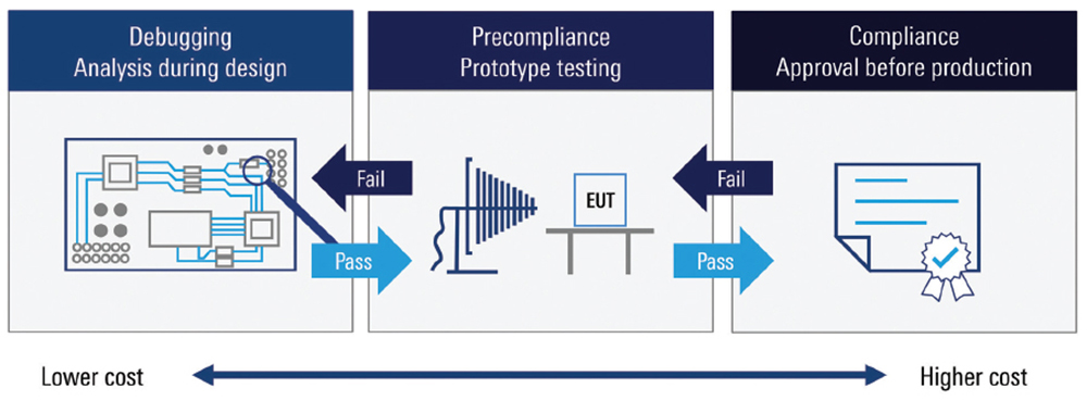
Figure 1 illustrates the electromagnetic compatibility (EMC) testing process. EMI debugging and analysis should be incorporated into the design process itself. If initial measurements do not reveal any serious issues, the equipment under test (EUT) moves into pre-compliance testing. The pre-compliance tests should come as close as possible to the associated compliance tests. If an EUT fails any of these pre-compliance tests, it goes back to the design and debugging phase for modification. Once pre-compliance tests have been successfully passed, the EUT then moves to full compliance testing at a lab or test house. Successfully passing the required compliance tests results in formal certification, allowing the device to be marketed.
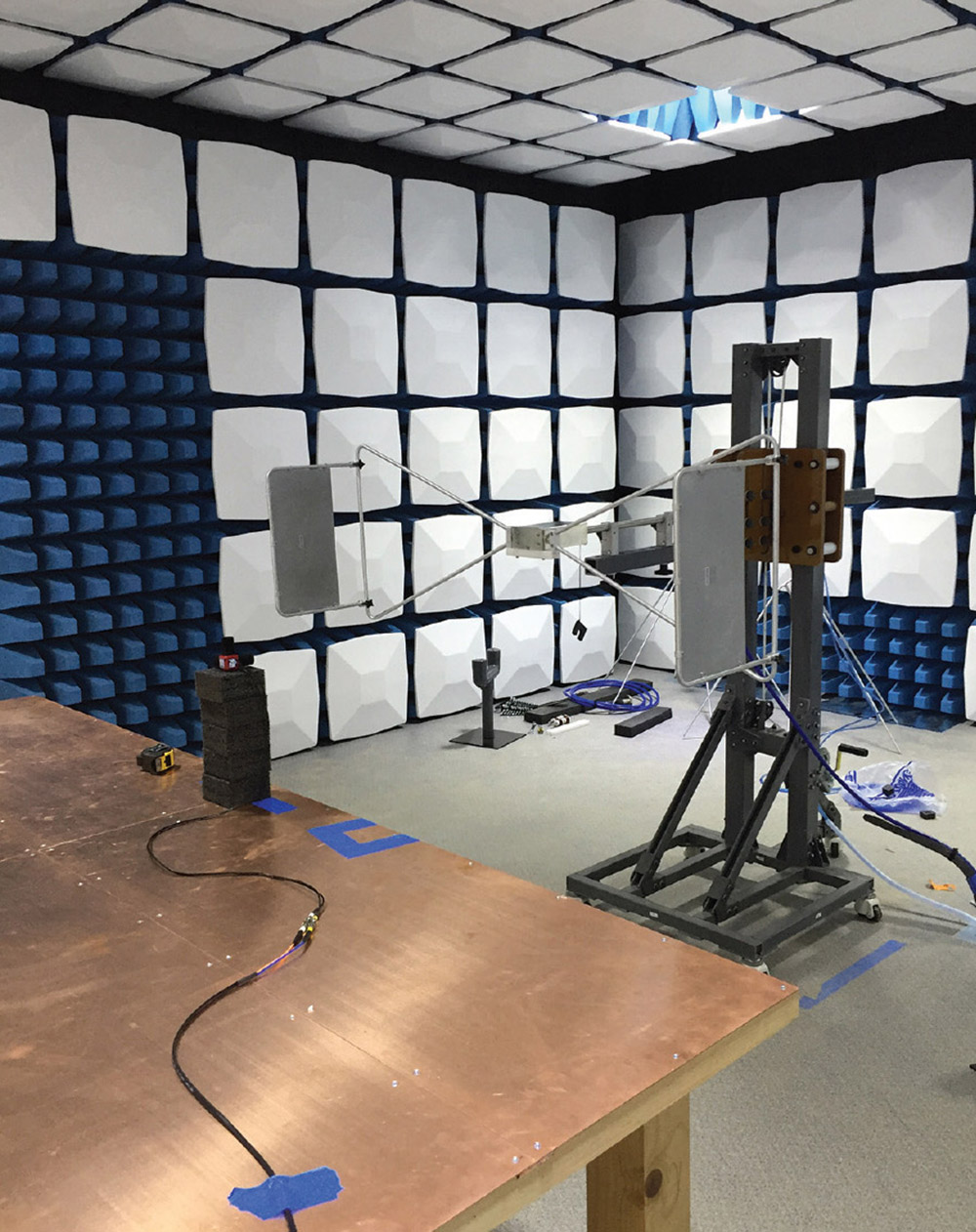
On the other hand, radiated EMI compliance testing generally requires a shielded chamber or a suitable open-air test site. Due to the size, cost, and complexity of configuring these types of facilities, most radiated pre-compliance tests cannot precisely duplicate the compliance test environment.
As a result, modifications are often made when performing radiated pre-compliance tests, such as adding margins to the measurement results. For example, a smaller chamber leads to higher emissions than in the final compliance test as the distance between the antenna and EUT is smaller. In this case, emission limits must be raised to take the stronger signals into account. Going from a typical compliance distance of ten meters to a typical pre-compliance distance of three meters, as shown in Figure 2, might require approximately 10 dB higher emission limits.
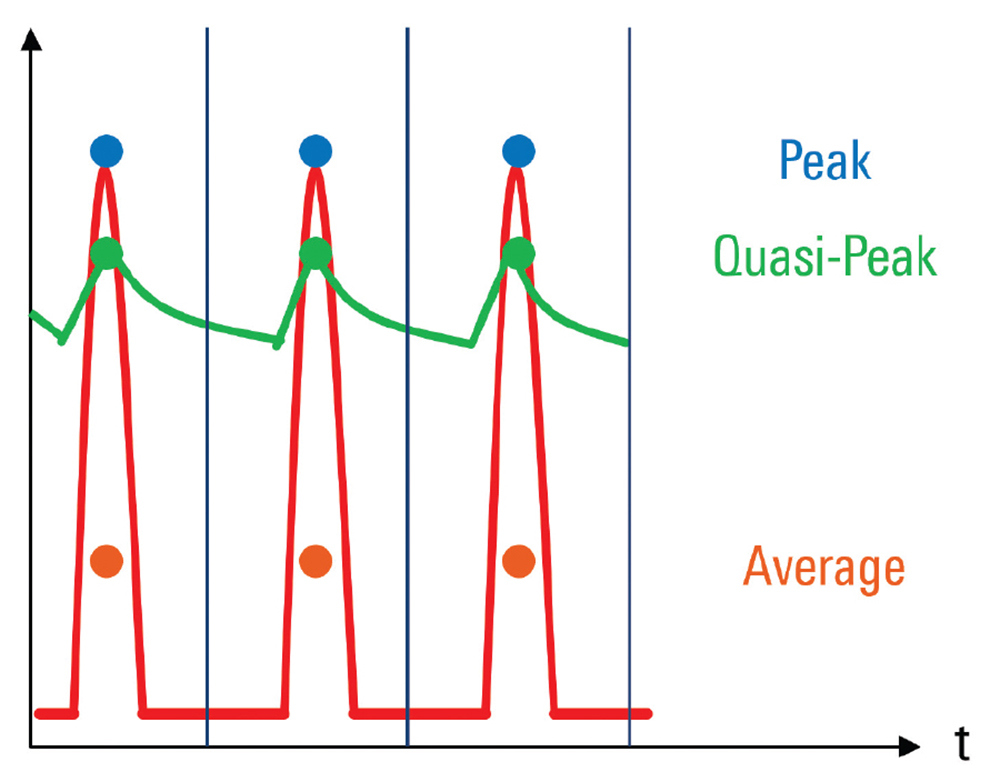
Measurements made with a peak detector are much faster than those made with a quasi-peak detector, usually by at least several orders of magnitude. Additionally, peak detector results are always higher than quasi-peak results. If an EUT passes pre-compliance testing using the faster peak detector, it will also pass the slower tests with a quasi-peak detector. For this reason, the peak detector is more common in pre-compliance testing and the quasi-peak detector is more common in compliance testing.
Spectrograms are useful because they show how signals change over time and over a range of frequencies. This enables easy identification of time-varying signal behavior such as drifting or frequency hopping. Spectrograms also make it easy to see small signals in the presence of larger signals. Most spectrum analyzers and EMI receivers have spectrograms as a standard feature, and spectrograms are also common for oscilloscopes when displaying frequency-domain information in so-called FFT (fast Fourier transform) mode.
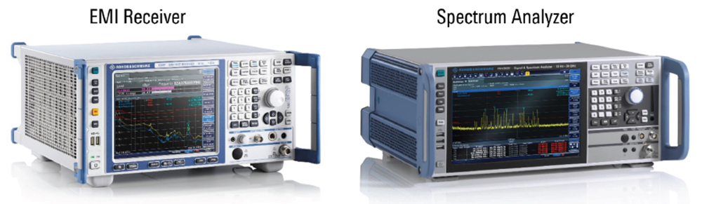
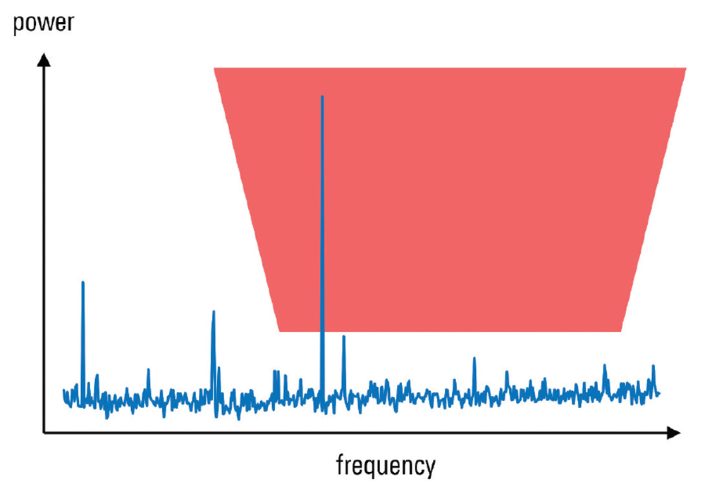
Preselection protects the first mixer. It is implemented as a switchable bank of filters that allows an EMI receiver to select only the frequencies of interest. The particular filter is chosen automatically by the receiver based on the configured input frequency. Many EMI standards require that the “measuring instrument” have preselection, and this is why compliance testing is performed with EMI receivers rather than with spectrum analyzers. Many spectrum analyzers also have a feature called preselection, but this is usually a high-pass filtering based on YIG technology and not a switchable filter bank.

Modern EMI receivers support time domain scans by splitting the measurement range into large spectrum blocks. The instrument digitizes and processes each of them by using FFT. Time domain scan provides a significant speed improvement over the stepped scan without sacrificing accuracy. Time domain scan has been approved for usage in most types of compliance testing and also can save significant time during pre-compliance testing.
One potential drawback of using oscilloscopes for pre-compliance testing is that they usually do not natively support limit lines, although limit lines and other EMI-related features can be implemented in external software.
Wide bandwidth and the ability to correlate time and frequency domain data make oscilloscopes very valuable for debugging issues discovered during pre-compliance testing. Features such as spectrograms and limit lines can be supported by all three instruments. EMI receivers additionally offer preselection and time domain scans. EMI receivers are used for full compliance testing and using them for pre-compliance tests leads to a closer correlation with compliance test results.
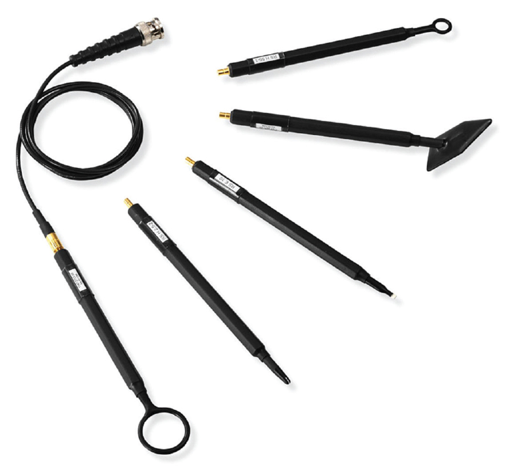
However, with regard to troubleshooting or debugging the causes of emissions, these types of antennas are not appropriate. They are too large and too bulky to provide precise information about which part or component of the EUT is generating non-compliant emissions.