
his is the second part of our article “(Re)Discovering the Lost Science of Near Field Measurements.” Part 1 of the article (see In Compliance Magazine, July 2023) explained what near and far field measurements entail, and that one-meter measurements are very much near field. This second part picks up where Part 1 left off, and explains the evolution of the earlier 12” and present-day one-meter separation measurements, considerations in antenna selection, and the difference between antenna-induced and field strength limits, and the evolution from one to the other.
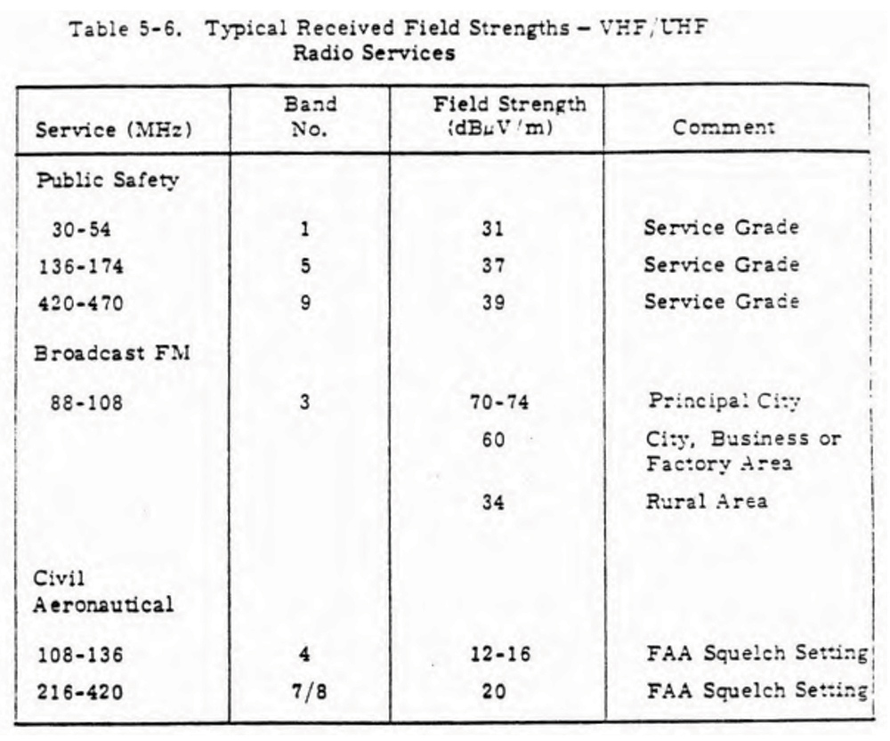
Figure 4 is an example excerpted from Reference 14. Such specifications state that a certain quality of baseband signal results when a specified level of broadcast signal is received. From this level, an EMI limit may be counted down using the signal-to-noise ratio required to get the specified baseband quality. Thus, it is completely natural to specify limits protecting such services in terms of field intensity, especially when the compliance measurement is made in the far field (or nearly so).
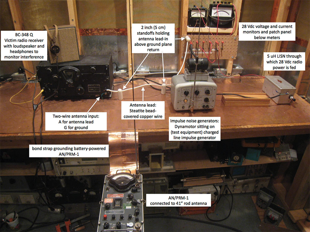
Rigorously, “antenna-induced” means the theoretical open-circuit voltage that would appear at the antenna terminals with an electric field impinging upon it. Losses associated with any circuitry necessary to adapt from that open-circuit potential to a signal that can be piped down a transmission line must be accounted for. So, with the 41” rod antenna used as in Figure 5, there is no data reduction necessary: the receiver meter reading (plus any attenuation selected) is the reading to be compared to the limit.
Of course, any cable losses must be accounted for as well, just as in a field intensity measurement. The concept of an antenna-induced limit may seem foreign, but there is a close modern example with which an EMC engineer should be familiar. Radiated emission measurements such as those described above are designed to force good EMC design at the equipment level, so that at system or platform integration, there are no ugly surprises resulting in delays or costly modifications at the last minute. The “proof of the pudding” is verification that all platform antenna-connected receivers can operate interference-free.
With such receivers often being tunable over thousands of channels, it is impractical to tune to and check each frequency. Instead, standards such as MIL-STD-464 mandate a “spectrum analyzer noise floor survey.”15 The transmission line connecting the receiver’s antenna is disconnected from the receiver, and instead attached to a spectrum analyzer or EMI receiver, which is set to sweep over the entire tunable range of the receiver, or multiple sub-bands if that is necessary. Signals appearing above the substituted receiver’s noise floor or some other level are then checked to see if they actually cause interference.
This is almost an antenna-induced measurement. The pass/fail criterion is a dBuV or more likely dBm level based on the particular receiver’s performance specification. A similar example may be found in the C & D revisions of MIL-STD-464, where antenna-induced measurements at a distance of one meter from Army ground vehicles are made using not EMI test antennas as in MIL-STD-461, but rather antennas representative of those next to which the ground vehicle might be parked (typically whips). The whips are connected to a spectrum analyzer, and the limit is again in terms of the rf potential or power at the connected spectrum analyzer.
One other important facet of antenna-induced limits and the passages from NADC-EL-5515 is worth mentioning here. NADC-EL-5515 went to some length to explain the selection of antennas used for MIL-I-6181B 12” measurements. They were supposed to simulate the coupling to platform antenna-connected conductors (open-wire transmission lines). If one looks at antennas used beyond the biconical frequency range in vehicle EMI testing today, one finds horns and log-periodic arrays. The simulation of platform antennas for a good quality radiated emission test uses antennas with dipole-like patterns, because such are either used on platforms, or in the case of high gain platform antennas, noise sources are typically in the back or at most side lobes of such, and thus are coupling via a low gain mechanism.
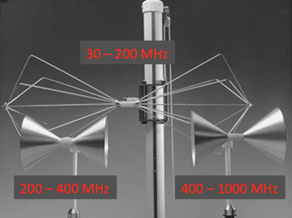
It is the author’s belief that biconical antennas such as the Compliance Design collection shown in Figure 7 would serve admirably. Even if antenna-induced limits were not invoked, it is the author’s opinion that such antennas are superior to what is used today above 200 MHz. With an antenna-induced limit, one could compare the output of the Figure 7 antennas to what would be required at a platform-level spectrum analyzer survey. Even without an antenna-induced limit, given the similarity between the EMI test and platform-installed antennas, one could do the comparison to get a much better prognostication of the actual EMC “proof-of-the-pudding” test results.

When the Tri-Service Committee convened circa 1966 to fashion MIL-STD-461/2/3 out of the various Service and platform-unique EMI specifications, they apparently deemed it time to abandon the 12” grandfather clause. Army and Navy EMI specifications of the time were already making some radiated emission measurements at distances greater than one foot, and the one-meter separation that resulted may have been nothing more than a “metricized” average of the Army (5’ minimum), Navy (3’) and Air Force (1’) separations.16, 17, 18, 19
MIL-STD-462 (1967) required the present one-meter separation between the test sample and the antenna.20 With an antenna as the radiated emission victim, as opposed to a transmission line, it might have seemed natural to transition to a field strength type control. Whatever the reason, the move to a one-meter separation was accompanied by a shift to a field intensity limit, and the consequent need for the kinds of antenna factors we use today. Thus, SAE ARP-958 was published in 1968; one year after MIL-STD-462 was released.
For the record, it should be noted that forerunners to RTCA/DO-160 included antenna-induced radiated emission controls.21, 22 RTCA/DO-160 was first released in 1975, and by that time field intensity limits had superseded antenna-induced, as described. Automotive radiated emission practice was always field intensity control but that did not begin until the 1970s.
Future installments of “(Re)Discovering the Lost Science of Near-Field Measurements” will discuss both theoretical and practical problems arising from the misapplication of field intensity and far-field concepts to near-field phenomena.
Endnotes
- CBEMA Report – CBEMA/ESC5/77/29 – “Limits and Methods of Measurement of Electromagnetic Emanations from Electronic Data Processing and Office Equipment,” 20 May 1977.
- MIL-STD-464 and newer, Electromagnetic Environmental Effects Requirements for Systems, 1997 – present.
- MIL-E-55301(EL), Electromagnetic Compatibility, 01 April 1965.
- MIL-I-16910A(SHIPS), Interference Measurement, Radio, Methods, and Limits, 14 Kilocycles to 1000 Megacycles, 30 August 1954.
- MIL-I-26600(USAF), Interference Control Requirements, Aeronautical Equipment, 02 June 1958.
- The late Steve Caine was the chairman of the Tri-Service Working Group that revised MIL-STD-461C (1986) and MIL-STD-462 (1967) into MIL-STD-461D and MIL-STD-462D in the 1989 – 1993-time frame. He introduced the committee to the public at the 1989 IEEE EMC Symposium in Denver, saying that as he was the last surviving member of the original committee that fashioned MIL-STD-461/2/3 back in the ‘60s, it fell on him to lead the effort to clean up the mess they had made of it. When he was asked at another time about how some of the MIL-STD-461 limits and -462 test methods came about back in the ‘60s, he sighed and said, “Well, there was a lot of horse-trading going on back then.”
- MIL-STD-462, Electromagnetic Interference Characteristics, Measurement of, 31 July 1967.
- RTCA/DO-119, Interference to Aircraft Electronic Equipment from Devices Carried Aboard, 12 April 1963.
- RTCA/DO-138, Environmental Conditions and Test Procedures for Airborne Electronic/Electrical Equipment and Instruments, 27 June 1968.
