
EMC concepts explained
Shielding to Prevent Radiation
Part 3: Far-Field Shielding Effectiveness of a Solid Conducting Shield – Exact Solution
T

his is the third of seven articles devoted to the topic of shielding to prevent electromagnetic wave radiation. The first article [1] discussed reflection and transmission of uniform plane waves at a normal boundary. The second article [2] addressed normal incidence of a uniform plane wave on a solid conducting shield with no apertures. The article concluded with the definition of shielding in the far field given by

equation
This article presents the exact solution to Equation (1). The subsequent article will present the approximate solutions.
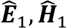
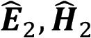
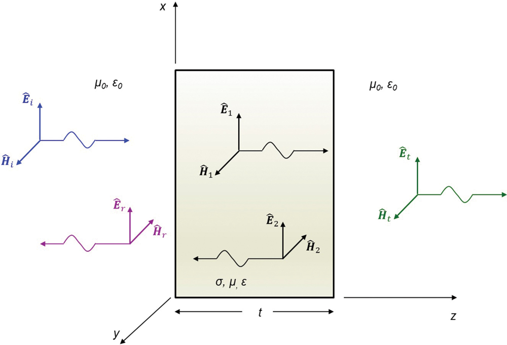
Figure 1 shows a conducting shield of thickness t, conductivity σ, permittivity ε, and permeability µ, surrounded on both sides by air (free space, and thus a perfect dielectric) [2]. Initially, there is no current density at the interfaces.
Uniform plane incident on a conducting shield
Figure 1: Uniform plane incident on a conducting shield
A uniform plane wave is normally incident on its left interface. Uniformity assumption, together with normal incidence, means that the shield is in the far field of the radiation source.

The incident wave, upon arrival at the left most boundary (), will be partially reflected () and partially transmitted () through the shield.

The transmitted wave (), upon arrival at the right most boundary, will be partially reflected () and partially transmitted () through the shield.

The reflected wave () propagates back through the shield and strikes the first interface, incident from the right.

In [2], the incident wave is described by

equation
equation
The reflected wave is described by
equation
equation
The wave transmitted through the left interface is described by
equation
equation
The wave reflected at the right interface is described by
equation
equation
Finally, the transmitted wave through the right interface is described by
equation
equation
The magnitude of incident field, , is assumed to be known. In order to determine the magnitude of the transmitted field, , we need to determine the magnitudes of the remaining waves, , , . Thus, we need four equations in four unknowns. These are generated by enforcing the boundary conditions on the field vectors at the two boundaries z = 0 and z = t.

Continuity condition of the tangential components of the electric fields at the left interface produces [3]


equation
or
equation
leading to
equation
Continuity condition of the tangential components of the magnetic fields at the left interface produces
equation
or
equation
leading to
equation
Continuity condition of the tangential components of the electric fields at the right interface produces
equation
or
equation
leading to
equation
Continuity condition of the tangential components of the magnetic fields at the right interface produces
equation
or
equation
leading to
equation
Thus, we need to solve four equations: (9), (12), (15), and (18), repeated here
equation
equation
equation
equation
Towards this end, let us divide Eq. (21) by to obtain
equation
Adding Equations (22) and (23) gives
equation
or
equation
from which we obtain as
equation
Subtracting Eq. (22) from Eq. (23) gives
equation
or
equation
From which we obtain as
equation
Next, let us divide Eq. (19) by η0 to obtain
equation
Adding Equations (20) and 30 gives
equation
or
equation
from which we obtain as
equation
Substituting for from Eq. (26) and from Eq. (29), we obtain

equation
or
equation
or
equation
or
equation
and thus
equation
Let us express the propagation constant as
equation
For a good conductor, the attenuation constant is related to skin depth by
equation
and thus the propagation constant becomes
equation
Using Eq. (40) in Eq. (37) gives
equation
and the shielding effectiveness becomes
equation
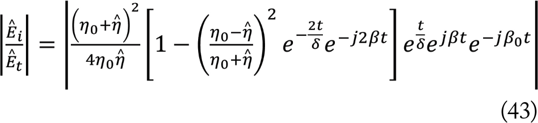
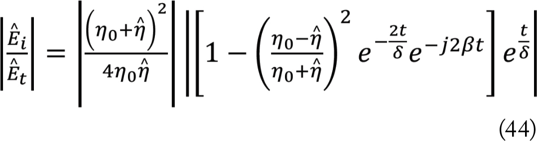
The magnitude of the shielding effectiveness is
equation
or
equation
or
equation
It is convenient to express the shielding effectiveness in decibels
equation
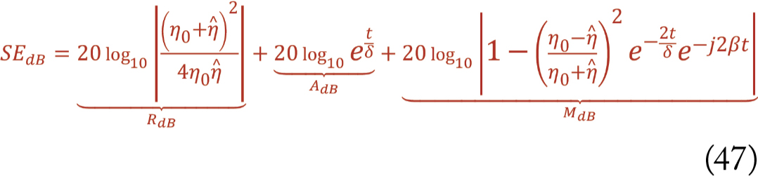
Then, utilizing Eq. (45), the shielding effectiveness in dB becomes
equation
or
equation
where RdB is called the reflection loss and represents the portion of the incident field that is reflected at the shield interface. It is given by
equation
AdB is called the absorption loss and represents the portion of the incident field that crosses the shield surface and is attenuated as it travels through the shield. It is given by
equation
MdB is called the multiple-reflection loss and represents the portion of the incident field that undergoes multiple reflections within the shield. It is given by
equation
The reflection and absorption losses are positive numbers (in dB), while the multiple reflection loss is a negative number (in dB). It, therefore, reduces the shielding effectiveness.

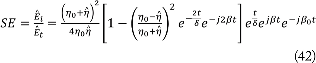
The solution in Equation (42) or Equation (47) was obtained for the shield made of a good conductor under the assumption of normal incidence of the uniform wave, i.e., when the shield is in the far field of the radiation source. The solution in Equation (42) or (47) is often referred to as the exact solution.

In the next article, we will make some reasonable approximations that will greatly simplify this solution without any significant loss of accuracy.

References
  1. Bogdan Adamczyk, “Shielding to Prevent Radiation – Part 1: Uniform Plane Wave Reflection and Transmission at a Normal Boundary,” In Compliance Magazine, June 2025.
  2. Bogdan Adamczyk, “Shielding to Prevent Radiation – Part 2: Uniform Plane Wave Normal Incidence on a Conducting Shield,” In Compliance Magazine, July 2025.
  3. Bogdan Adamczyk, Principles of Electromagnetic Compatibility – Laboratory Exercises and Lectures, Wiley, 2023.

Share this story:
Bogdan Adamczyk headshot
Dr. Bogdan Adamczyk is professor and director of the EMC Center at Grand Valley State University (http://www.gvsu.edu/emccenter) where he performs EMC educational research and regularly teaches EM/EMC courses and EMC certificate courses for industry. He is an iNARTE-certified EMC Master Design Engineer. He is the author of two textbooks, “Foundations of Electromagnetic Compatibility with Practical Applications” (Wiley, 2017) and “Principles of Electromagnetic Compatibility: Laboratory Exercises and Lectures” (Wiley, 2024). He has been writing “EMC Concepts Explained” monthly since January 2017. He can be reached at adamczyb@gvsu.edu.