Securing the Patients: Cybersecurity Standards for Connected Medical Devices
The Engineer’s Test Lab Handbook
Securing the Patients: Cybersecurity Standards for Connected Medical Devices
The Engineer’s Test Lab Handbook

RF solution will do!

Booth #311
Peace of mind
A fully compliant system from AR includes an engineered design that is guaranteed to meet field strength requirements for the tests. Contact our design team to discuss your requirements and get a custom proposal.


ISSN 1948-8254 (print)
ISSN 1948-8262 (online)
is published by
Same Page Publishing Inc.
451 King Street, #458
Littleton, MA 01460
tel: (978) 486-4684
fax: (978) 486-4691
© Copyright 2025 Same Page Publishing, Inc. all rights reserved
Contents may not be reproduced in any form without the prior consent of the publisher. While every attempt is made to provide accurate information, neither the publisher nor the authors accept any liability for errors or omissions.
editor-in-chief
Please contact our circulation department at circulation@incompliancemag.com
NBC News reports that the FDA’s newly launched AI tool, named Elsa, is already having challenges addressing even simple tasks, such as uploading documents or answering questions from users. Further, the report says that the agency’s AI tool is not yet connected to the Internet, limiting its ability to access newly published studies. NBC’s sources say that Elsa “still needs significant work” to become operational…
According to a press release on the country’s government website, the new PMS regulations will require device manufacturers to proactively track the performance and safety of their products. The new regulations, which took effect on June 16th, apply to all UKCA- and CE-marked devices…

rom the time that Heinrich Rudolf Hertz first demonstrated the transfer of electrical energy from one antenna to another in the late 1880s, humanity has witnessed, observed, and enjoyed the fruits of electromagnetic radiated fields. The electromagnetic waves first produced by Hertz in his lab in 1886 were proof that James Clerk Maxwell’s 1864 theory of “electromagnetic waves” was correct.
Hertz published a series of papers in the last years of the 1880s that verified the characteristics of the “Hertzian Waves” with respect to frequency, amplitude, speed (velocity of light), and other physical parameters. Hertz never realized the practical importance of his discovery and did not explore the applications of the “Hertzian Waves,” which became known as “radio waves” over time.
However, many premier scientists of the day did recognize the importance of the discovery, including Guglielmo Marconi, Nikola Tesla, Edwin Armstrong, Lee DeForest, and many others.


aval platforms present the most severe Electromagnetic Environment (EME) in the world, created by high-powered electromagnetic emitters such as air-search, surface-search, fire-control, and navigation radars, as well as broadband communications and electronic warfare systems. The limited space available aboard surface platforms necessitates that these high-powered electromagnetic emitters be located in proximity to other electronic/electrical systems aboard ships. Sensitive electronic equipment is typically contained within Radio Frequency (RF) reflective cavities (i.e., below-deck spaces, equipment enclosures, etc.) for protection from harsh EMEs. Communications and power cables are typically routed between enclosures within such spaces, introducing inadvertent coupling paths between cavities. Additionally, as the topside EME continues to increase and as below-deck transmitters (i.e., RFID, Wi-Fi, etc.) are incrementally installed within the Fleet, understanding and predicting the field distributions within coupled spaces will assist in characterizing electronic equipment performance and assuring personnel safety.
Statistical electromagnetic formalisms for electromagnetic fields within RF-reflective cavities had their beginnings through the study and use of reverberation chambers (RCs) for Electromagnetic Compatibility (EMC) testing [1] and are now widely accepted within the EMC community as a tool for compatibility and susceptibility testing [2-4]. RCs are electromagnetically reflective cavities with a high quality (Q) factor where the fields excited within the cavity reverberate [4-6]. The addition of tuners within the chamber (also known as paddles or stirrers) allows for the electromagnetic (EM) boundary conditions to be easily changed so the EM fields can be perturbed discretely (mode-tuned) or continuously (mode-stirred).


Raleigh, North Carolina

- 200+ Technical Sessions
- Hands-on Learning
- Ask the Experts Panel
- Live Demonstrations
- Exhibit Hall Showcase
- Networking Opportunities
Engineers, researchers, and industry professionals will explore a broad range of timely topics, including AI, biological EMC, nanotechnology, wireless power transfer, and cybersecurity, alongside foundational EMC and SIPI principles. Attendees can expect more than 30 workshops and tutorials, special sessions, expert panels, and the ever-popular hands-on experiments and demonstrations. A dedicated “Standards Week” will bring focus to global EMC and SIPI standardization efforts, while Global University programs offer structured educational paths for early-career and seasoned professionals alike.
A standout moment of the week will be the keynote address by Professor Christian Schuster of Hamburg University of Technology, who will explore the convergence of EMC and SIPI engineering—a timely and thought-provoking reflection on the evolving nature of the discipline. With a full exhibit hall showcasing the latest innovations in test equipment, software, and lab services, there’s no shortage of opportunities to discover new tools and connect with the companies shaping the future of compliance and performance.
As a publisher deeply rooted in this space, we attend EMC+SIPI year after year because it is the definitive event for staying ahead of emerging challenges and solutions in electromagnetic compatibility and signal integrity. This symposium is more than a conference—it’s where theory meets practice, ideas spark innovation, and professional communities grow stronger. Whether you’re seeking technical advancement, professional development, or collaboration opportunities, EMC+SIPI 2025 is the place to be.

- EMC Measurements
- Signal & Power Integrity
- EMI Control
- EMC Management
- Low Frequency EMC
- High Power Electromagnetics
- Electromagnetic Environments
- Smart Grid EMC
- Regulatory Requirements for EMC, ESD, EMI, and SIPI

Keynote Presentation Speaker
Christian Schuster, Hamburg University of Technology
General Chair, IEEE 2025 International Symposium on Electromagnetic Compatibility, Signal & Power Integrity (EMC+SIPI)
Technical Program Chair, IEEE 2025 International Symposium on Electromagnetic Compatibility, Signal & Power Integrity (EMC+SIPI)
- Biomedical Devices
- DC Electrification / Microgrids
- EMI/EMC issues for transportation electrification
- Wireless Charging
- Intentional EMI and Cybersecurity
- AI/ML for EMC and SIPI Problems

- Global SIPI University
- Clayton R. Paul Global University
- Technical Sessions
- Workshops
- Tutorials
- Technical Papers
- Special Sessions
- Ask the Experts Panel
- Experiments and Demonstrations
- Standards Week
- Student Hardware Design Competition
- Technical Tours
- Collateral Meetings
- Technical Committees
- Welcome Reception
- Evening Gala
- Awards Luncheon
- Chapter Chair Training Session and Luncheon
- Past Presidents Luncheon
- Team EMC Bike Ride
- IEEE EMC Society Women in Engineering Event
- Young Professionals Networking Event
- Youth Technical Program: Biomedical Engineering
- Companion Club & Tours
What sets the Global EMC University apart is its interactive format, encouraging dialogue between instructors and participants for a more personalized learning experience. Beyond the classroom, the program also offers valuable networking opportunities, connecting attendees with fellow professionals dedicated to mastering the science of electromagnetic compatibility. For engineers aiming to advance their knowledge and career, this program offers a concentrated path to success.


Get your Insider’s guide to navigating the exhibit floor, discovering industry expertise, and where to find the fun! Pick up your guide at registration or visit us at Booth 515.

Each year, it brings us great joy to see and meet with many of our readers, authors, and advertisers as they visit our booth to pick up the latest issue of the magazine and collect their annual In Compliance t-shirt. This in person opportunity allows us to connect with many engineering professionals to discuss the latest challenges and learn valuable tips, solutions, and updates.
This year, as we commemorate our 16th year in publication, we reflect on what an honor it is to be your trusted source of electronic product compliance information. We are proud to deliver In Compliance every month in both print and digital formats! And as always you will find a steady stream of content online, in between magazine issues. All of this is possible because of support from our advertising partners, contributors and reader community, and for that we are eternally grateful.
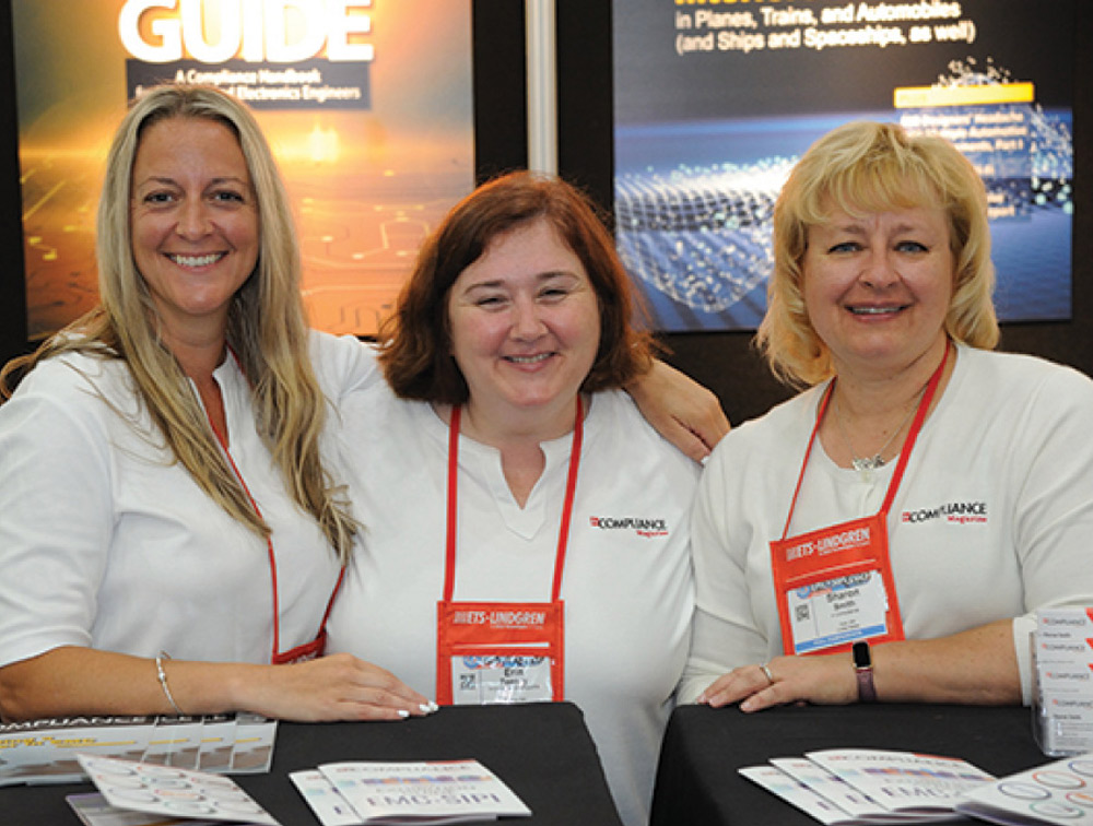
Photo copyright: Jerry Ramie


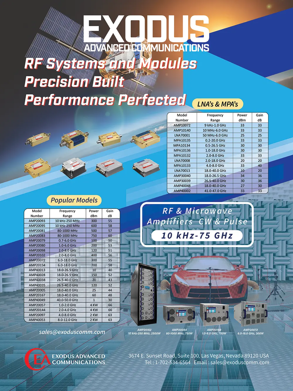
- Frequencies from 10 KHz to 40 GHz.
- Power Levels from 1 W to 25 kW.
- All Ophir RF Solid State Amplifiers come with a 5-year Warranty.
- All Ophir RF Amplifiers are designed and manufactured in the USA.
Drop by our Booth #402 to discuss how we can assist you in your power and testing requirements.

n the age of digital health, connected medical devices are transforming patient care. From insulin pumps and glucose monitors to smart inhalers and wearable ECGs, these devices deliver real-time data, enable remote monitoring, and improve clinical outcomes. However, as connectivity increases across devices, so does the risk of cyber attacks. For engineers tasked with designing these devices, security by design is more imperative than ever for compliance.
Consider a scenario in which a hacker exploits a vulnerability in a Bluetooth-enabled insulin pump. The attacker could alter dosage settings or disable alerts, putting the patient at serious risk. Such vulnerability issues are made possible due to the increased entry points from devices,2 leaving those who use clinician-recommended technologies for care susceptible to attacks.


hether you’re trying to get a product through safety approval from one of the many Nationally Recognized Testing Laboratory’s (NTRLs) or having full compliance EMC testing performed at an accredited or non-accredited third-party laboratory or an internal in-house test facility, it’s imperative for successful completion of the project that as a compliance engineer or technician leading a product certification effort, you trust but verify the work of these other entities. For the remainder of the article, we’ll call these other entities “service providers.”
If investing in a new system isn’t the right move right now, NSI-MI’s Test Services offer a powerful alternative. You’ll gain access to the same advanced technology, precision environments, and expert support—without the upfront commitment. Our dedicated test service facilities are designed to deliver consistent, high-quality results, helping you move projects forward with confidence. With controlled conditions and expert oversight, we ensure your measurements are not only accurate—but truly meaningful.
Our advanced test ranges include:
- Compact Antenna Test Range (Atlanta, GA): Ideal for multi-purpose and far-field measurements, supporting frequencies from 2 to 50 GHz and devices up to 1.8 meters in diameter.
- Combo Near‑Field Range (Los Angeles, CA): A versatile system supporting planar, cylindrical, and spherical near-field testing from 1 to 110 GHz, accommodating devices up to 3.6 meters.
- Spherical Near‑Field Ranges (Los Angeles, CA): Covering frequencies from 300 MHz to 110 GHz, these ranges are optimized for high-precision measurements of complex antenna systems.
Whether you’re validating phased array performance, calibrating near-field probes, or preparing for terminal operations certification, NSI-MI is your trusted partner for RF testing. We specialize in the characterization of antennas, radomes, and RF devices across a wide range of industries including aerospace, defense, wireless, and automotive.
Don’t leave your RF performance to chance. Partner with NSI-MI for reliable, high-precision testing.
rob.mercer@ametek.com | https://www.nsi-mi.com/test-services
Rob Mercer
+1 678-542-2546
rob.mercer@ametek.com
https://www.nsi-mi.com/test-services


Element Materials Technology operates advanced battery testing labs offering comprehensive services for batteries used across industries like automotive, aerospace, consumer electronics, medical devices, and energy storage. These labs ensure batteries meet stringent safety, reliability, and performance standards, especially for lithium-ion, lithium-metal, and solid-state technologies.


With facilities worldwide, Element provides testing close to manufacturing and distribution hubs, enhancing efficiency and speed to market. By tailoring testing programs and guiding clients through certification, Element helps companies deliver safe, reliable, and high-performance battery solutions for global markets.
Contact:
contact.us@element.com
(888) 786-7555
https://www.element.com/connected-technologies/battery-testing-services

Our lab specializes in the characterization of static dissipative properties for products and materials, adhering to all major ESD standards—including ANSI/ESD, MIL-STDs, IEC, and other internationally recognized benchmarks. This ensures that materials used in manufacturing and handling meet critical ESD control requirements, providing essential protection for sensitive electronic devices.
A cornerstone of our capabilities is product qualification testing in accordance with ANSI/ESD S20.20. This is performed within our ISO 17025-compliant laboratory, featuring calibrated ESD test instrumentation, temperature- and humidity-controlled gloveboxes, and a dedicated controlled environment room. Our processes are carried out by highly trained technical personnel who ensure precision, repeatability, and compliance at every stage.
In addition, we offer reliability and ESD susceptibility testing of devices and systems using Human Body Model (HBM), Charged Device Model (CDM), and Machine Model (MM) simulators. These tests are vital for compliance assessments, failure analysis, and design verification, and are conducted in alignment with ANSI/ESD and JEDEC standards. This helps clients identify vulnerabilities early and validate robustness under realistic ESD scenarios.
Our team of experienced ESD Program Managers and ESD Electrical Engineers brings a unique level of customization to every project. From consumer healthcare products like nasal gel to complex aerospace hardware such as satellite components, our staff tailors evaluations to the specific needs of your application. We pride ourselves on being a collaborative partner throughout the testing lifecycle—offering not only results but insight and guidance.
Through a combination of accredited processes, specialized environments, and industry-leading expertise, our test lab plays a pivotal role in ensuring product integrity and performance in ESD-sensitive environments. Whether for compliance, R&D, or product development, our lab delivers trusted results that support innovation, reliability, and customer assurance.
Contact:
Lisa Pimpinella
info.eosesda@esda.org
(315) 339-6937
https://www.esda.org/eosesd-association-services-llc
https://www.element.com/connected-technologies
- Atlanta-Gainesville, GA
- Brooklyn Park, MN
- Dallas Plano, TX
- Irvine, CA
- Washington, Columbia, Oakland Mills
- Medical Devices
- Test and Measurement Equipment
- Battery
- Product Safety
- EMC Testing
- International Compliance
- NRTL
- ISO/IEC 17025 (A2LA)
- CB Testing Laboratory (CBTL)
- Largest commercial cell and battery cycling capacity
- Large Drive in EMC Chambers
- Full service environmental testing services in addition to EMC, NRTL, and CBTL
https://www.esda.org/eosesd-association-services-llc
- ESD Testing
- Static Dissipative Properties Characterization
- Consumer Healthcare to Aerospace Applications
- Product Qualification Testing (ANSI/ESD S20.20)
- ESD Susceptibility Testing (HBM, CDM, MM)
- Compliance Assessments
- Failure Analysis
- ISO/IEC 17025
- ANSI/ESD, MIL-STDs, IEC, JEDEC Standards
- Temperature and humidity-controlled gloveboxes
- Dedicated controlled environment room
- Experienced ESD Program Managers and Engineers
- Customized testing solutions across diverse industries
https://www.nsi-mi.com/test‑services
- RF Testing
- Antenna Characterization
- Radome Testing
- Phased Array Performance Validation
- Near-Field Probe Calibration
- Multi-purpose and Far-field Measurements
- Planar, Cylindrical, and Spherical Near-field Testing
- Terminal Operations Certification
- RF Device Characterization
- A2LA-Accredited Processes
- NIST-Traceable Calibration
- Compact Antenna Test Range
- Combo Near-Field Range
- Spherical Near-Field Ranges
- Purpose-built controlled test environments


his is the third of seven articles devoted to the topic of shielding to prevent electromagnetic wave radiation. The first article [1] discussed reflection and transmission of uniform plane waves at a normal boundary. The second article [2] addressed normal incidence of a uniform plane wave on a solid conducting shield with no apertures. The article concluded with the definition of shielding in the far field given by

A uniform plane wave is normally incident on its left interface. Uniformity assumption, together with normal incidence, means that the shield is in the far field of the radiation source.
The incident wave, upon arrival at the left most boundary  )
) )
) )
)
he new connector standard USB-C includes both power delivery of current up to 20 V as well as SuperSpeed data lines. Integrated circuits (ICs) receiving signals on these data lines are very ESD sensitive. The Vbus pins in the USB-C connector are placed directly next to the SuperSpeed Tx and Rx pins, which poses the risk that the data pins can temporarily short to the supply voltage. The USB-C specification requires a mandatory AC coupling capacitor placed on the data lines in front of the IC when USB4 is used on the SuperSpeed lines. Thus, transient voltage suppressor (TVS) devices for system-level protection can be placed either behind the AC coupling capacitor or in front of it.
In this article, the effect of the TVS placement and the device properties on the IC is investigated. Special PCBs have been produced; one is shown in Figure 1. The distance between TVS and an IC replacement consisting of a 2-ohm resistor and a forward-bias diode is varied. The voltage at the IC can be measured. The IC residual current is determined by measuring the voltage drop across the resistor. Six different TVS protection devices have been chosen. All of them have a capacitance of less than 0.2 pF, which makes them suitable for the SuperSpeed application. Two of them are placed in front of the capacitor. However, to avoid turning on during a short to the power line, these TVS devices require a breakdown voltage larger than 20V. For a placement behind the capacitor, a high breakdown voltage is not needed. An overview of the TVS parameters is shown in Table 1.

recently heard an amusing quote from a colleague: “When it comes to EMC simulation, no one believes the results—except the person who did the simulation. When it comes to EMC testing, everyone believes the results—except the person who ran the test.” Anyone who’s worked in the field of EMC will probably smile knowingly at that.
Thanks to advancements in simulation tools, it’s now possible to build fairly accurate models using 3D solvers to simulate conducted emissions, radiated emissions, surface currents, and more. But such simulation tools come at a price—not only in terms of expensive software licenses (which often puts them out of reach for small to medium-sized companies), but also the steep learning curve. Whoever runs these simulations needs to thoroughly understand the product and its circuitry—including parasitics, physical layout, and component behavior—and must also be skilled in building the simulation model itself. A good model can take weeks, even months, to develop. And after all that effort, how do you validate it? You still need test results to back it up.
As a practical engineer, I often lean more toward hands-on diagnostics. To paraphrase a well-worn saying: “My best simulation tool is my soldering iron.” (Though in the EMC world, maybe we should say: “My best simulation tools are my near-field probes and current clamps.”)


You can do that here.
ESD Best Practices for Technology Change!
August 11-14
Auditing Your Laboratory to ISO/IEC 17025: 2017
August 11-14
Understanding ISO/IEC 17025: 2017 for Testing & Calibration Labs
August 18-22
2025 IEEE International Symposium on Electromagnetic Compatibility, Signal & Power Integrity (EMC+SIPI)
 Visit In Compliance at Booth 515!
Reverberation Chambers: Introduction, Basic Theory, Uses and Applications
August 28
Radio Regulations for Module Integrators
View Index