Techniques

Location of Safety Warnings: On the Product or in the Manual?
Location of Safety Warnings: On the Product or in the Manual?

ISSN 1948-8254 (print)
ISSN 1948-8262 (online)
is published by
Same Page Publishing Inc.
451 King Street, #458
Littleton, MA 01460
tel: (978) 486-4684
fax: (978) 486-4691
©Copyright 2021 Same Page Publishing, Inc. all rights reserved
Contents may not be reproduced in any form without the prior consent of the publisher.
While every attempt is made to provide accurate information, neither the publisher nor the authors accept any liability for errors or omissions.
publisher
editor
bruce@brucearch.com
keith.armstrong@
cherryclough.com
Leo@EisnerSafety.com
dgerke@emiguru.com
ken.javor@emcompliance.com
kenrossesq@gmail.com
wernerschaefer@comcast.net
Bogdan Adamczyk
adamczyb@gvsu.edu
On Your Mark
Erin Earley
eearley@clarionsafety.com
Subscriptions outside North America are $129 for 12 issues. The digital edition is free.
Please contact our circulation department at circulation@incompliancemag.com

white paper provided by

white paper provided by

Block Electromagnetic Waves
for Products


hen helping clients in the electric vehicle (EV) industry with their module design, I often find that engineers tend to follow an out-of-date list of “do’s” and “don’ts” in the form of EMC design rules without understanding the basics. These kinds of design rules are often borrowed from other industries, and they are not up to date with the latest technology involved in the fast-paced EV industry.
In this article, using a powertrain module as an example, I will first introduce the high voltage EMC regulations with which a powertrain module needs to comply. I will then highlight the risks and challenges when designing such modules. The main part of this article will share design techniques that engineers can apply on various parts of a powertrain module, including ground, front-end filter, inverter design, and so on. Examples are given to demonstrate some of the key design techniques.
It should be noted that the introduced design techniques in this article share the same principles as any other EMC engineering. Therefore, engineers from other industries can also benefit from these techniques.
It’s a better solution.
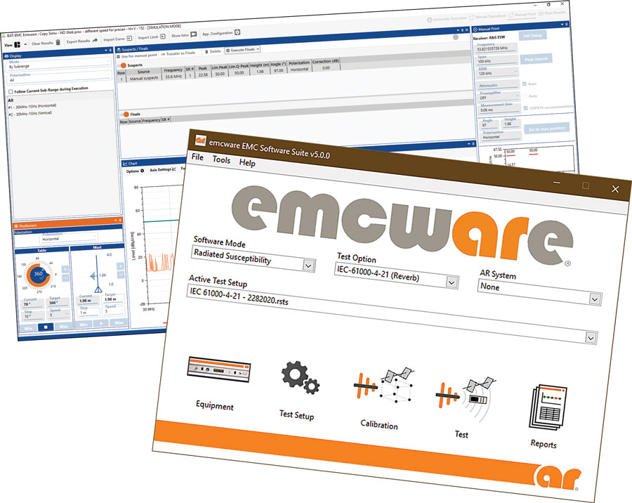
At today’s AR, we’re not just developing solutions to satisfy one software need. We’re working hard to satisfy all your emc software needs, bringing together two great products as part of our commitment to offering a total solution: emcware® 5.0 and Nexio BAT-EMC®.
With emcware 5.0, you get over 500 test profiles, a streamlined user workflow which reduces set-up and training time, and reporting templates to get you up and running faster than ever. In addition, emcware now includes reverb immunity test methodologies.
If customization is what you’re looking for, AR now offers Nexio BAT-EMC. In-depth equipment management options and custom reporting and testing profiles gives you complete flexibility.
It’s just one more way we’re bringing you the best solutions. At AR, we’re with you all the way.
To schedule a demo, visit www.arworld.us/emcware or call us at 215-723-8181.
Other ar divisions: modular rf • sunar rf motion • ar europe
Copyright © 2020 AR. The orange stripe on AR products is Reg. U.S. Pat. & TM. Off.
Other ar divisions: modular rf • sunar rf motion • ar europe
Copyright © 2020 AR. The orange stripe on AR products is Reg. U.S. Pat. & TM. Off.
ver the last decade, automotive original equipment manufacturers (OEMs) like Ford, GM, and Tesla have been at the forefront of mobility and advanced driver assistance systems (ADAS), jockeying for a leadership position in this hotly contested, quickly developing field. As these systems advance, with them comes an increase in the number of semiconductor components in the vehicle to support devices like cameras, radars, and modules used to make decisions based on their information.
This has provided an opportunity for semiconductor manufacturers to increase their market share, allowing them to pivot from their traditional base microcontroller (MCU) offerings to highly integrated system on chip (SoC) processors, memory, and power devices. However, as the industry evolves, the question remains for both consumers and OEMs alike: ”How can we standardize the development and design of these components across the industry, such that we can satisfy the risk that comes along with these components, while confidently claiming the part functionally safe?”


To view our accreditations and case studies, visit our website at ets-lindgren.com.
Location of Safety Warnings
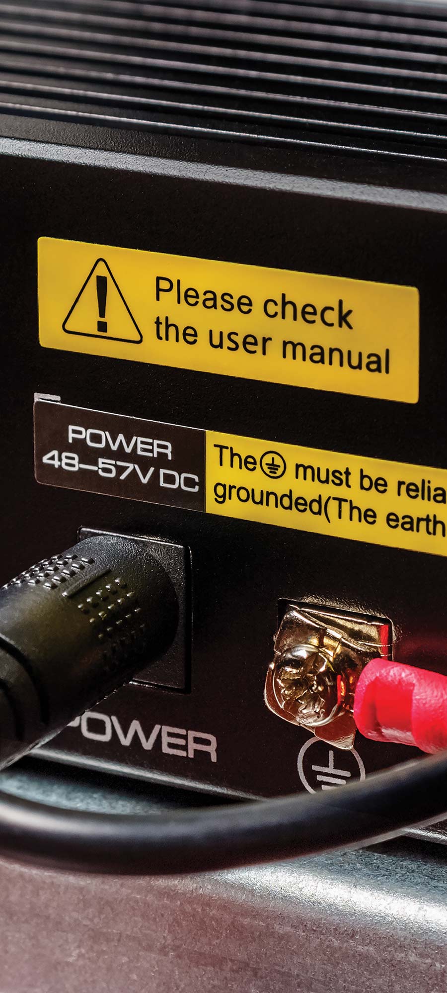
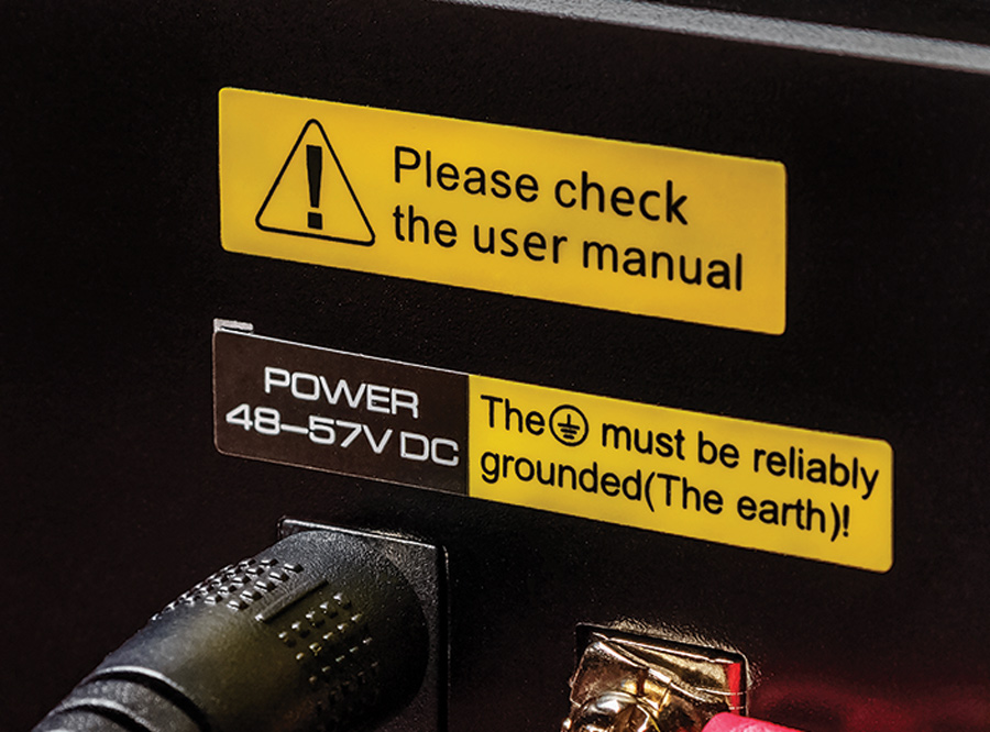
n important issue to be considered in trying to meet the duty to warn and instruct is for the manufacturer to decide where to place safety warnings – on the product, in the manual, or on the product and in the manual. Generally speaking, all warning labels on the product should be shown in the manual. But the converse is not true. Not all warnings in the manual need to be placed on the product.
Since our first goal is to communicate the warning to the user, we need to figure out where best to place them to maximize the possibility of that happening. In the event of an accident, the plaintiff will always claim that they did not see the warning and, therefore, the manufacturer may need to present evidence as to why they placed it where they did.
This article will discuss the basic duty to warn and instruct, and then examine the law and standards as they pertain to this issue. Then it will discuss recommendations about how to decide where to place this information and what to say.
Part I: Non-Ideal Passive Components
his article is part of a two-article series devoted to the concept of resonance in EMC. In Part I the fundamental circuit background is presented and illustrated by the resonance phenomenon in the non-ideal models of passive circuit components: capacitors, ferrite beads, resistors, and inductors. Part II (to appear in the next issue) describes the resonance in the decoupling capacitor circuits.
Actual circuits differ from these classical configurations; in addition to the intentional discrete reactive components, they contain distributed parasitic inductances and capacitances. Nevertheless, the study of these basic RLC configurations provides an insight into the more complex topologies and their behavior. Let’s begin with a series RLC circuit.
The obvious changing trends in display technology are products getting thinner and lighter and flexible display devices. There is a common trend for higher resolution and pixels per inch (PPI) and increasing screen sizes for new display devices. Also, there are continuous developments for brighter, lower reflectance displays for better visibility under high ambient light conditions. Future display trends will continue to be introduced at industry trade shows including Internationale Funkausstellung (IFA) and International Consumer Electronics Show (CES). Some of the newer technologies and finished products are Quantum Dots, curved and flexible displays with higher resolution and higher pixels per inch, Low-temperature polycrystalline silicon (LTPS) and Indium gallium zinc oxide (IGZO) technology, OLED, and transparent display technologies.
Product Safety and the Pandemic
he pandemic has brought many changes in the way we do business. For equipment manufacturers, that may equate to big picture shifts related to your supply chain, vendors, and production. At the time of writing, COVID-19 continues to surge; even once the virus is better contained, though, its impact in areas like those will likely have a lingering effect for some time to come. Here, let’s explore key considerations to keep in mind for your product safety strategy, warnings, and instructions.
“Over the past months, a common trend we’ve seen with product manufacturers is the need to reevaluate their supply chains to ensure they’re well-positioned to continue business despite hurdles with the current environment – everything from vendor shutdowns to issues with fulfilling orders,” says Angela Lambert, who consults with product safety teams on a regular basis through her role heading standards compliance at Clarion Safety Systems.

A number of people who had been enjoying weightless activities in the non-spinning central hub of Virgin Space Ltd’s newest hotel “Arthur C Clarke III” found themselves trapped on the ‘ceiling’ for 15 minutes, unable to reach the doors…
The 30nm silicon fabrication process is now well-established and helping create many products and provide services that even ten years ago would have been considered science fiction. But investigations by York University into claims…
An example of a subtle change in hardware configuration to the original design concept can be found in a life vest. The life vest was fielded with a bridgewire EID that could be fired by a salt-water activated battery pack that had been hardened…
Even though all the (ESD test) generators have peak current values and risetimes very similar to the ones specified in the standard, some of the generators fail the equipment under test (EUT) at vastly different voltage levels from…
Military Standard 810 (MIL-STD-810) Testing Open Course
March 2-4
Fundamentals of Random Vibration and Shock Testing
March 22-26
EUCAP 2021 – The 15th European Conference on Antennas and Propagation
April 5-9
EMC Week
April 22-23
Principles of Electromagnetic Compatibility
EMC+SIPI 2021
May 11
Annual Chicago IEEE EMC MiniSymposium
May 13
EMC Fest 2021
May 19-20
EMC & Compliance International 2021 Workshop
Outstanding Service
- Anechoic Chambers
- RF Shielded Enclosures
- Reverberation Chambers
- Relocation/Modification
- Upgrades
- Chamber Testing
- Deployable Enclosures
- Repair/Maintenance
5185 Dolman Ridge Road
Ottawa, ON
613-841-1663/1-800-EMC-1495
3446 Winder HWY, Suite M334
Flowery Branch, GA
1-800-EMC-1495 x342
Impasse de la Manille, 56470
La Trinité-sur-Mer, France
5185 Dolman Ridge Road
Ottawa, ON
613-841-1663/1-800-EMC-1495
3446 Winder HWY, Suite M334
Flowery Branch, GA
1-800-EMC-1495 x342
Impasse de la Manille, 56470
La Trinité-sur-Mer, France


