olving EMI problems isn’t only about ensuring that a product can meet EMC regulations and standards (although it’s a significant part of the job). Another crucial reason for addressing EMI issues is to enhance product reliability, especially when a product operates in public or industrial areas where there are many different types of noise sources.
European and international immunity standards are based on typical operating environments and statistical data. Meeting these standards should be considered the minimum requirement for reliable equipment operation in the real world, given the increasing electromagnetic interference levels.
A product that incorporates EMC considerations from the beginning may not necessarily perform better, but its immunity to interference will improve its reliability in the field and make installation easier. This also leads to fewer service calls, particularly those troublesome “no fault found” cases that consume valuable time. It also reduces warranty costs and enhances customer perception, resulting in increased repeat business.
To address this intermittent issue, the first step was to analyze the ambient electromagnetic noise. In such environments, various devices like fans and pumps are typically driven by variable speed drives (VSDs), which can produce noise ranging from a few kHz to about 100 MHz. However, these noise sources are usually continuous and don’t align with the intermittent timer trip outs.
Another characteristic of such environments is that inductive loads, like motors and relays, generate voltage spikes or kickback voltages each time they’re switched off. These spikes can appear on the public mains network and also signal lines (via near-field coupling). The IEC 61000-4-4 standard tests such phenomena using electric fast transient (EFT) events coupled to the device under test (DUT) via a CDN (to the power port) or a capacitive coupling clamp (to the signal port).
In this case, the second characteristic seemed to align more with the field failures. To troubleshoot a potential transient failure, an EFT/Burst generator or an ESD simulator was needed. (An ESD simulator set to 10 or 20 pulses per second may be used to approximately simulate EFT pulses as suggested in [1], though the pulse shapes between the two types are quite different.)
Not all companies have an EFT/Burst generator or a capacitive coupling clamp, but one can rent a generator from a specialized EMC rental company. A quick way of testing the signal port without using a clamp is to directly connect the CDN output of the EFT generator to the signal port while keeping the voltage level moderate (starting with 200V and staying below 1kV). That approach proved effective in this case (Figure 1).
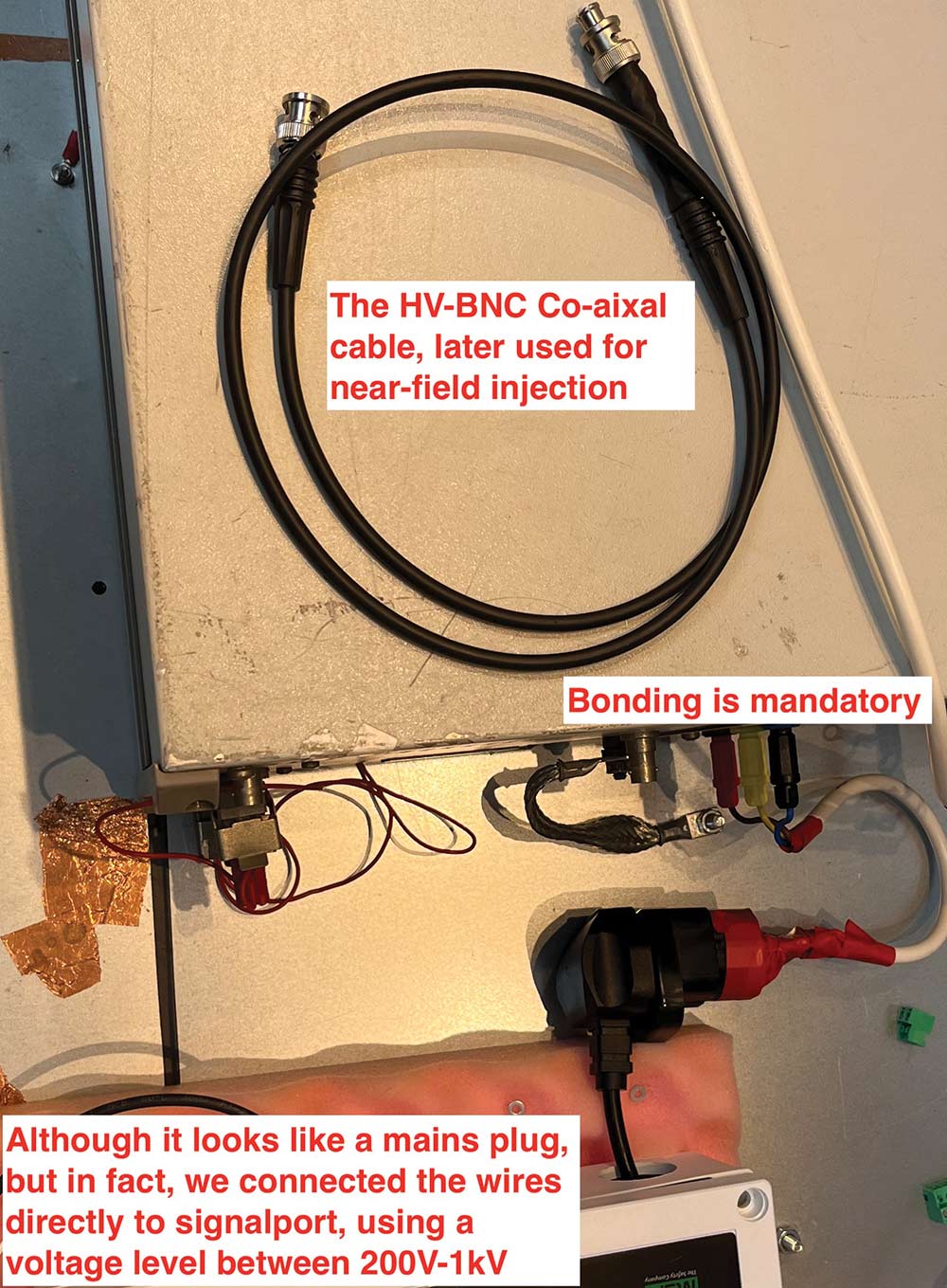
- Ensure the coaxial cable connected to the EFT/Burst HV output uses a suitable connector (e.g., SHV) due to the HV nature.
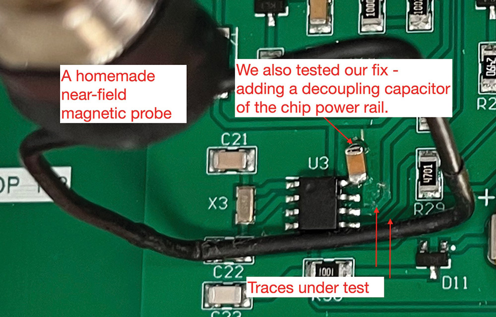
- If a commercial near-field probe designed for HV operation isn’t available, engineers can create their own probe, ensuring proper insulation.
- The ground side of the loop must be securely connected to the shield of the coax from the pulse generator to prevent open circuit voltage issues.
- When using a near-field probe, it’s advisable not to exceed 1kV of the EFT/Burst generator’s output.
In this case, we provided the following recommendations for fixing the issues:
- Adding ferrite cores on the signal input cables.
- Adding a decoupling capacitor (100nF) on the power rail of the chip, as shown in Figure 2.
- For the next revision of the PCB, re-route critical traces, adding C-L-C filters on the signal ports.
- Ken Wyatt, Workbench Troubleshooting EMC Immunity (Volume 3).
- Douglas C. Smith, “Noise Injection for Design Analysis and Debugging.” https://emcesd.com/pdf/DC09_DCSmith.pdf