A Circuit Model for the Charged Device Model Spark
Expert Insights
EMC Concepts Explained
Hot Topics in ESD
Troubleshooting EMI Like A Pro
A Circuit Model for the Charged Device Model Spark
Expert Insights
EMC Concepts Explained
Hot Topics in ESD
Troubleshooting EMI Like A Pro

solid-state amplifiers


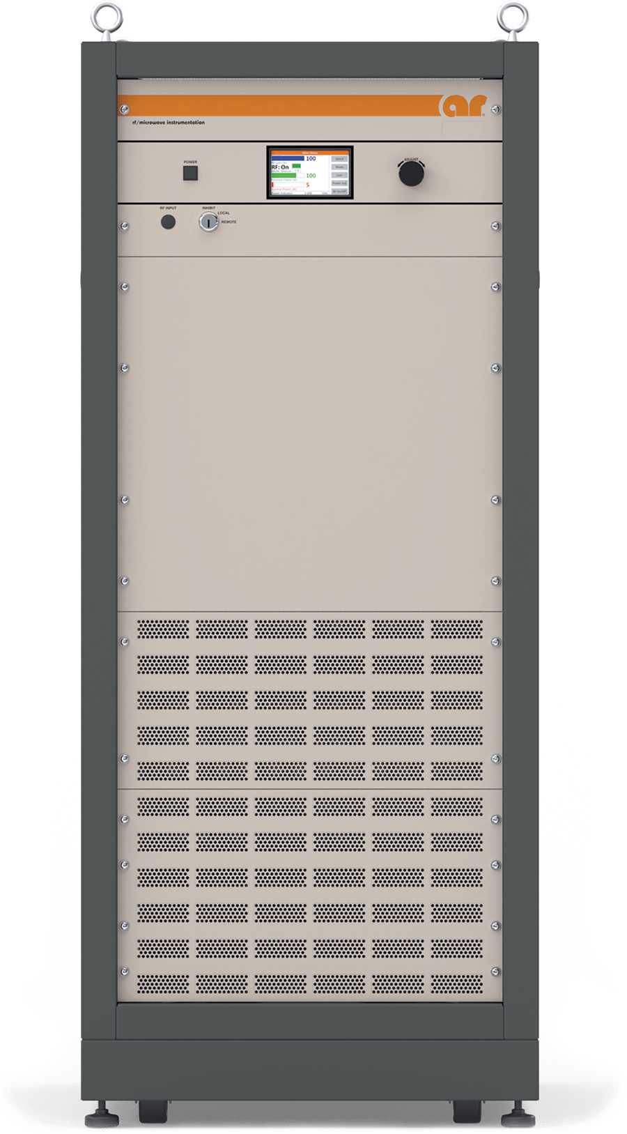
- HIRF (High-Intensity Radiated Field) Testing
- NEMP (Nuclear Electromagnetic Pulse) Testing
- EW (Electronic Warfare) Jamming and Jamming Simulation
- Component Testing
- EW (Electronic Warfare) Destruction
- Radar and radar simulation

ISSN 1948-8254 (print)
ISSN 1948-8262 (online)
is published by
Same Page Publishing Inc.
451 King Street, #458
Littleton, MA 01460
tel: (978) 486-4684
fax: (978) 486-4691
© Copyright 2024 Same Page Publishing, Inc. all rights reserved
Contents may not be reproduced in any form without the prior consent of the publisher. While every attempt is made to provide accurate information, neither the publisher nor the authors accept any liability for errors or omissions.
editor-in-chief
Please contact our circulation department at circulation@incompliancemag.com
So-called FM booster stations allow broadcasters to differentiate the programming that they air to certain geographic sections within their entire service areas. Originally used primarily for rebroadcasting transmission signals to areas where reception is poor, booster technology has now evolved to the point that broadcasters can use boosters…
The FDA’s pilot program will provide both consumers and industry with early alerts regarding the recall of potentially high-risk medical devices used in connection with cardiovascular, gastrorenal, obstetrical or gynecological, and urological issues…


ost engineers are familiar with near‑field probes and that they are sensitive to E- or H-fields emanating from circuit boards, cables or enclosure seams. They are really the first order of business when evaluating a circuit board or system. A more advanced characterization technique is to not only identify the major energy sources, but to interpret different emission types observed. That’s the purpose of this article.
Figure 1 shows a standard set of four probes from Beehive Electronics. The pointed one is an E-field probe, while the three circular examples are H-field probes in various loop diameters.
A set of near-field probes may be obtained from many other sources, including Aaronia AG, Com-Power, Langer EMV-Technik, Rigol, Rohde & Schwarz, and Siglent.
his month’s blog is pulled from the product safety playbook. It highlights a potential issue to avoid when considering an optocoupler’s creepage distance when placed onto a printed circuit board (PCB).
Recall that the purpose of an optocoupler is to provide isolation of the hazardous voltages present on one side of a circuit from reaching the non-hazardous elements on the other side of the circuit, and creepage distance is the shortest distance along the surface of a solid insulating material between two conductive parts (IEC 60664-1:2020).
If the proper creepage distance is not maintained, then not only is there a potential safety issue with the end-product resulting in the product failing NRTL certification (and the subsequent delay to releasing it to production), or worse, the issue going un-noticed and placing product in the field that has a potential safety issue.
irst, the Line Impedance Stabilization Network, or LISN (pronounced “listen”), is not intended to be a filter. Although it can function as a bit of a filter, please do not use it in this manner. The original intent was to simulate the line impedance found on aircraft power lines. The work was first performed by Alan Watton, who worked on the Douglas DC-3 type aircraft during WWII.[1] This was originally a 5 µH LISN design, which the RTCA and most aircraft manufacturers still use. The LISN has been used in military and aerospace testing since the early 1953’s. The 5 µH LISN was first used in MIL-I-6181B (29 May 1953). It was also used in DO-138 (1967) and may have been used earlier.
This ubiquitous use of LISNs has provided another benefit, which I believe is more important: The use of a standardized test setup and power line impedances allows testing to be performed and replicated at different testing laboratories and hopefully find the same or similar results. When everyone uses the same source line impedance, cable lengths, ground planes, and standoffs, the ability to reproduce the emission measurements provides assurance that the results can be trusted. [2]
Earlier versions of DO-160 included the schematic for the LISN, whereas DO-160D and later versions included only the impedance curve, with a note stating that a 10 µF capacitor may be needed on the power line side of the LISN to achieve the low frequency impedance required. The modified schematic is shown in Figure 1.
Part 1

n 1967, while on patrol in the Gulf of Tokin, the United States Navy Carrier USS Forrestal was executing wartime missions over North Vietnam. At 10:45 AM local time, the ship was preparing to launch more than 27 A-4 Skyhawk and F-4B Phantom Fighter jets, all fully fueled and armed with a mixture of iron bombs, precision missiles, and Zuni rocket launchers. At 10:51 AM, an F-4B experienced an un-commanded Zuni missile launch on the flight deck, striking a neighboring A-4 and starting a fire causing a series of devastating secondary explosions. Quenching the fire nearly capsized the ship, which was ultimately saved through the heroics of the sailors who served aboard the Forrestal.
Although the US Navy conducted an extremely thorough accident investigation, many follow-up technical articles in the aerospace and NASA literature, including current EMI design books, blamed the initiation event on EMI from on the on-board AN/SPS-43 VHF search radar. This article is aimed at reinforcing the official USN record regarding the accident’s true root cause. The Forrestal’s many “lessons learned” led in part to the creation of an entirely new discipline called “insensitive munitions” within the Electromagnetic Compatibility community and is therefore a critical event to understand.


IL-STD-461 RE102 is probably the most commonly failed test in the aerospace/defense world, with 50-90% of units failing their first pass testing. This is a frequent cause of schedule delays, first for troubleshooting, and then for all the meetings needed to process waivers. There are ways that it can be tailored, even very early in the product development process, to minimize the need for waivers after test failures. Any time a unit fails a test but is allowed to move forward after going through a waiver process, it’s an indication that the requirements were not set appropriately at the beginning of the program.
Ultimately, we want to do the minimum amount of testing that gives us the best assurance of mission success. We don’t want to over test and jeopardize cost and schedule targets. But we also don’t want to under test and miss something that could cause issues on the integrated platform. Understanding the purpose behind RE102 requirements helps us tailor them in a program-specific way.


he JEDEC/ESDA charged device model (CDM) test standard JS-002 places a component in a metal/dielectric test fixture and uses a field-induced air discharge to test each pin of the component. Current waveforms depend on the circuitry under test, yet are fairly consistent for the small and large CDM verification targets, metal disks specified by JS-002. Those waveforms often fit a simple 2-pole RLC circuit model as shown in Figure 1, and as summarized in our 2014 paper [1].
For these RLC fits to CDM waveforms, the R2 (common statistical figure-of-merit) can fall far short of the ideal value of 1.0, sometimes as low as R2 < 0.7 for large targets, representing a very poor fit. Clearly, something else is going on. Many workers have attempted to find clear trends in resistance R (presumed to be the spark resistance) but have not been able to do so. Field simulations of the CDM test fixture impedance have uncovered the expected skin effects, propagation delays, and high-frequency resonances. But, in the end, an L-C approximation holds out to several GHz. Thus, the calculated step response of the fixture and a metal target with constant R (presumably spark resistance) is close to a 2-pole RLC fit because the verification targets in the fixture have a principal resonant frequency of 1-2 GHz or less. The CDM spark itself is therefore thought to cause the observed deviations. Even when the agreement to RLC modeling is close (as can happen for the small target), the inductance L is higher than calculated for the probe and fixture (6-8 nH instead of 4-4.5 nH, for example).

his is the first of two articles devoted to the topic of capacitor impedance evaluation from the s parameter measurements using a network analyzer. Part 1 describes the impedance measurements and calculations from the s11 parameter using the one-port shunt method, two-port shunt, and two-port series methods. Part 2 will discuss impedance measurements and calculations using the s21 parameter with two-port shunt and two-port series methods.

he normal world is full of electrostatic discharge (ESD) risks to unprotected ESD susceptible devices (ESDS). To handle these, we must set up an ESD Protected Area (EPA) in which we have reduced the ESD risks to a low level. In Part 1, this article will look at how static electricity works. Part 2 will look at how we control it in an EPA.
Where does static electricity come from? Science tells us that every material is made of atoms. Atoms are made of electrical charges – positive protons in the atomic nucleus and negative electrons around them. When these are present in equal numbers, their electrical effects cancel.
When two materials touch, some charges move from one material to the other. When the materials separate, each takes a small surplus of one type of charge. Repetition can build the charge imbalance. The charges will try to move to restore balance if they can, but if prevented – static electricity starts to accumulate.


In Product Insights, Don MacArthur dives deep into practical EMI mitigation challenges, offering solutions for capacitor behavior, ferrite selection, differential probes, and more to optimize designs and advance engineering careers.
Ken Wyatt’s EMC Bench Notes helps engineers identify and resolve EMC issues early in the design cycle using in-house pre-compliance testing tools, enhancing troubleshooting skills and reducing costly testing failures.
Patrick Andre’s Military and Aerospace EMC shares valuable insights into EMC challenges in high-stakes environments like defense, aerospace, and military systems, offering engineers practical solutions and expertise.
Karen Burnham’s Standards Practice explores immunity standards and advanced testing methods, helping engineers navigate compliance challenges in industries like defense, aerospace, and automotive with techniques like reverberation chamber testing.
Kimball Williams’ Signals and Solutions connects the foundational techniques of amateur radio, such as Morse code, to modern EMC engineering, offering fresh perspectives on troubleshooting, testing, and innovation.
https://incompliancemag.com/expert-insights
lectromagnetic interference (EMI) issues that engineers encounter in the field are often due to poor layout design, with grounding layout problems being one of the primary contributors. From a radio frequency (RF) perspective, even a path with seemingly low resistance can present significant impedance. When RF currents are forced through this high-impedance path, a substantial RF voltage difference can develop. This voltage difference across what should be a common low-impedance ground can elevate noise levels.
This issue arises at both the printed circuit board (PCB) level and the system level. In this month’s column, we examine system-level troubleshooting techniques commonly used to identify grounding issues. We also demonstrate how improvements to system grounding can effectively reduce noise.
In this case study, the equipment under test (EUT) is a bi-directional power converter that uses two IGBT-based drive systems to deliver large bursts of power for mission-critical applications. As shown in Figure 1, we set up an on-site conducted emission test using a 32A three-phase LISN. Figure 1 also displays the initial conducted emission scanning results, showing several frequency bands where the EUT failed to meet compliance.


At home.
on the go.
You can do that here.
View Index