lectromagnetic compatibility (EMC) testing of e-drives and e-axles at the component level per CISPR 25 requires both technical measures and carefully developed implementation strategies to ensure that measurements accurately reflect real-world performance. Given the rising demands on performance classes, particularly for high-power electric axles, these tests require a setup that closely resembles the e-axle’s actual in-vehicle installation conditions. Achieving this realistic test setup presents unique challenges, as the scale and complexity of the test object directly impact the design and setup of the test bench.
For realistic testing, it is essential to account for the mechanical and spatial demands of larger e-axle systems. This often necessitates a significantly larger test bench than those typically used for conventional automotive components. Such an expanded setup results in increased metal structures within the test environment, specifically in the anechoic chamber. This added metal can influence the electromagnetic field distribution, potentially introducing reflections and resonances that affect measurement accuracy. Thus, ensuring that metallic elements do not interfere with the EMC results is a primary concern in the test bench design.
Another critical factor is the routing of cable harnesses. In many test benches, these cables must be routed near the metallic structures of the test setup. Ideally, they should be placed at the standardized length specified by CISPR 25 on the table’s ground plane. However, this proximity to metal surfaces can lead to unintended electromagnetic coupling and alter the interference profile, creating additional challenges for measurement precision.

The findings from our investigation highlight the complexities and potential variabilities involved in EMC testing for electric drives and axles, particularly when different test benches yield slightly different results. Consequently, this study aims to initiate a broader discussion on the standardization and reproducibility of measurement results for electric drives and axles across diverse test environments. By sharing these findings, we hope to encourage further research into optimizing EMC test setups and, ultimately, to foster more standardized and comparable testing practices for e-drive systems.
- Test environment: The test environment should be controlled and free from external electromagnetic interference. CISPR 25 tests are typically performed in shielded rooms or anechoic chambers to allow compliant testing and meet the ALSE verification in the defined frequency range.
- Grounding and bonding: Proper grounding and bonding are essential to ensure accurate testing results. Test setups must replicate the actual grounding conditions of the vehicle to achieve realistic results, especially for devices that are connected to the vehicle chassis or grounded to it.
- Cable and harness layout: The layout of cables and wiring harnesses used during testing should be as close as possible to the actual installation in the vehicle. This includes considerations like spacing, routing, and orientation of the cables to replicate in-vehicle conditions.
- Frequency range and limits: CISPR 25 specifies emission limits for various frequency bands (typically from 150 kHz to 2.5 GHz), which are relevant for automotive systems. It’s crucial to know the frequency range required by the component and ensure compliance with specified limits.
- Measurement equipment and probes: Use CISPR 25-compliant measurement equipment, like antennas, line impedance stabilization networks (LISNs), and RF probes, to ensure consistent and accurate results. Each piece of equipment must be calibrated to meet CISPR standards.
- Radiated and conducted emissions: CISPR 25 covers both radiated and conducted emissions. Radiated emissions testing focuses on the electromagnetic field emitted from the device, while conducted emissions testing measures noise on power or signal lines. Ensure that the test setup properly isolates and measures each type of emission as required.
- Power supply considerations: Use a stable and regulated power supply to replicate the vehicle’s electrical environment. Automotive components are often tested at different voltages (e.g., 12V, 24V) to ensure they meet CISPR 25 standards under typical operating conditions.
- Component mode of operation: Test the component in all its possible modes of operation. The device should be tested in idle, active, and any special modes to ensure it meets standards across its entire functional range.
- Compliance with test levels: CISPR 25 defines various test levels for different types of devices and applications. Selecting the correct test level is crucial based on the component’s placement in the vehicle and its susceptibility to or generation of electromagnetic interference.
- Data logging and analysis: Comprehensive logging of results, including peak, average, and quasi-peak values, is essential. Accurate data analysis will determine compliance with CISPR 25 standards and help identify any specific issues needing mitigation.
However, considering those crucial aspects of CISPR 25, testing can present a difficult challenge, especially when accounting for the component mode of operations that are required for e-motors or e-axles, as well as its correct and impact-free implementation into an EMC environment.
Furthermore, according to CISPR 25, a setup for e-axles is normatively not defined. Unlike conventional automotive components, e-axles can combine an electric motor, inverter, and transmission, which often create complex interactions between these subsystems in terms of electromagnetic emissions. The lack of a dedicated normative setup in CISPR 25 means that engineers must pay close attention to how the test bench is designed, as the setup itself can significantly influence test results.
Influencing parameters in the design of test benches for e-axle systems include the arrangement of high-voltage cables, grounding and bonding practices, motor positioning, and cooling systems, each of which can affect EMC performance. For instance, cable layouts and connections must realistically mimic in-vehicle conditions to ensure accurate emissions measurements, as real-world installations are influenced by the vehicle’s metallic structure and shielding effects. Proper grounding and bonding of the e-axle and all associated components are also essential, as this can mitigate or amplify emissions depending on the test bench’s design.
Considering these issues, e-axle EMC tests at the component level aim to replicate installation conditions as closely as possible. Yet, they often fall short of simulating the entire electromagnetic environment of a vehicle. To address this, system-level tests based on CISPR 12 (applicable to whole vehicles) may provide more realistic insights into how an e-axle will perform once installed. CISPR 12 considers radiated emissions for the entire vehicle and can reveal potential integration issues that might not be evident in isolated component testing. This broader testing approach may also highlight interactions between the e-axle and other on-board systems, such as power electronics, battery systems, and auxiliary electronics, each of which can contribute to the vehicle’s overall electromagnetic emissions.
While conducting CISPR 12 tests at the vehicle level offers valuable insight into the real-world EMC behavior of e-axles, these tests are complex and resource-intensive. Therefore, engineers must carefully balance the thoroughness of the EMC testing process with the time and cost constraints typical of automotive development cycles.
- Routing the cable harness close to metallic structures
- Using ferrites to minimize signal reflections
- Positioning the antenna near metallic structures
- Injecting a 120 dBµV signal within the 150 kHz to 1 GHz frequency range
- Measuring emissions, including consideration of the antenna factor
- Comparing the results to the CISPR 25 reference level to determine any deviations
- Ensuring compliance by achieving 90% of all measured points within a ±6 dB tolerance band


These findings emphasize the need for additional investigations into the effects of metallic structures on EMC testing environments, particularly for e-drive and e-axle systems. It would be valuable to conduct broader studies across various EMC test benches used for e-drives and e-axles, considering that such systems often operate under high-power conditions and involve complex electromagnetic interactions. Such studies could lead to optimized test setups that better reflect real-world performance, improve measurement reliability, and support more accurate compliance assessments for automotive EMC standards.


- Adherence to normative standards: Ensure all relevant normative requirements are met to achieve international compliance and recognition.
- Minimization of metallic structures: Avoid large metallic structures, especially above the ground plane, as they can affect measurement accuracy.
- Optimal cable harness placement: Maximize the distance between the cable harness and metallic structures and avoid parallel routing to reduce electromagnetic interference.
- Multi-directional measurements: Conduct measurements from multiple directions around the test object to obtain a comprehensive understanding of emissions.
- Minimal metal structure: Keeping metal structures within the EMC system as compact as possible to reduce interference.
- Shielded connections: Using shielded shafts for connections between the external load machines and the anechoic chamber.
- Optimized shaft length: Keeping the shaft connection to the 90° angle gear short, while maintaining the required distances from absorbers per CISPR 25.
- Flexible test table positioning: Allowing the test table to be positioned laterally for e-axle testing or perpendicular to focus on the periphery and cable harness.
- Integrated load machines: Where possible, embedding load machines into the floor can further reduce structural interference.
- Impact of metallic structures on cable harnesses: Metallic structures near the cable harness strongly influence emission results and can introduce errors.
- Limited effectiveness of absorptive materials: Using ferrite materials provides only partial compensation for metallic influence and is effective only up to 1 GHz.
- Criticality of structures above the ground plane: Metallic structures above the ground plane are particularly influential, creating resonance points that significantly alter results.
- Reproducibility challenges: Variations in size and placement of metallic structures above the ground plane can lead to major, often non-reproducible changes in results, highlighting the need for further investigation.

However, there is a need for further investigation and standardization. We advocate for updates to the CISPR 25 standard to address the unique challenges of testing electric axles, ensuring that consistent and reproducible testing methodologies are available to all OEMs and service providers globally. Establishing a unified approach to test procedures, equipment, and environmental conditions would improve test reliability and comparability, creating a standard that supports the rapid evolution of electric mobility.
Several additional factors should be considered for adapting CISPR 25 to better support e-axle testing. For example, the specific positioning of antennas is critical for accurately capturing emissions, while simulating dynamic driving conditions could provide more realistic insights into how these systems will behave under real-world operating conditions. Increased automation in test setups, both in terms of measurement and equipment handling, could improve efficiency and reproducibility.
Integrating e-axle test benches into an EMC testing environment requires detailed preparation of the anechoic chamber and careful selection of the medium used to simulate passive or active load on the test object. Depending on the setup, this could involve electrical, hydraulic, or pneumatic loading methods. Additionally, the spatial needs of the test setup, both within and outside of the EMC testing environment, should be considered, as e-axle testing equipment may require substantial space due to load machines, auxiliary systems, and ventilation requirements.
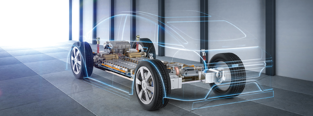
Our investigation is based on the needs of OEMs or service providers who specialize in e-motor and e-axle EMC tests. We, in partnership with other industry colleagues, advocate for finding a practical investigation of a solution for testing electric axles, which can be implemented with various suppliers of load machines. The focus of the solution is on the correct implementation of the knowledge gained within an EMC test environment and on the reproducibility of EMC tests. The renderings presented in this article offer different expansion options. But, most importantly, they represent a realistic technical conception and offer practical implementation strategies.

