his is the final article in a series [1-7] devoted to the topic of shielding to prevent electromagnetic wave radiation. All the previous articles assumed a solid shield with no apertures. This article addresses the impact of slots or apertures in the shield on radiation. It is shown that apertures can be as effective radiators as antennas of the same dimensions.

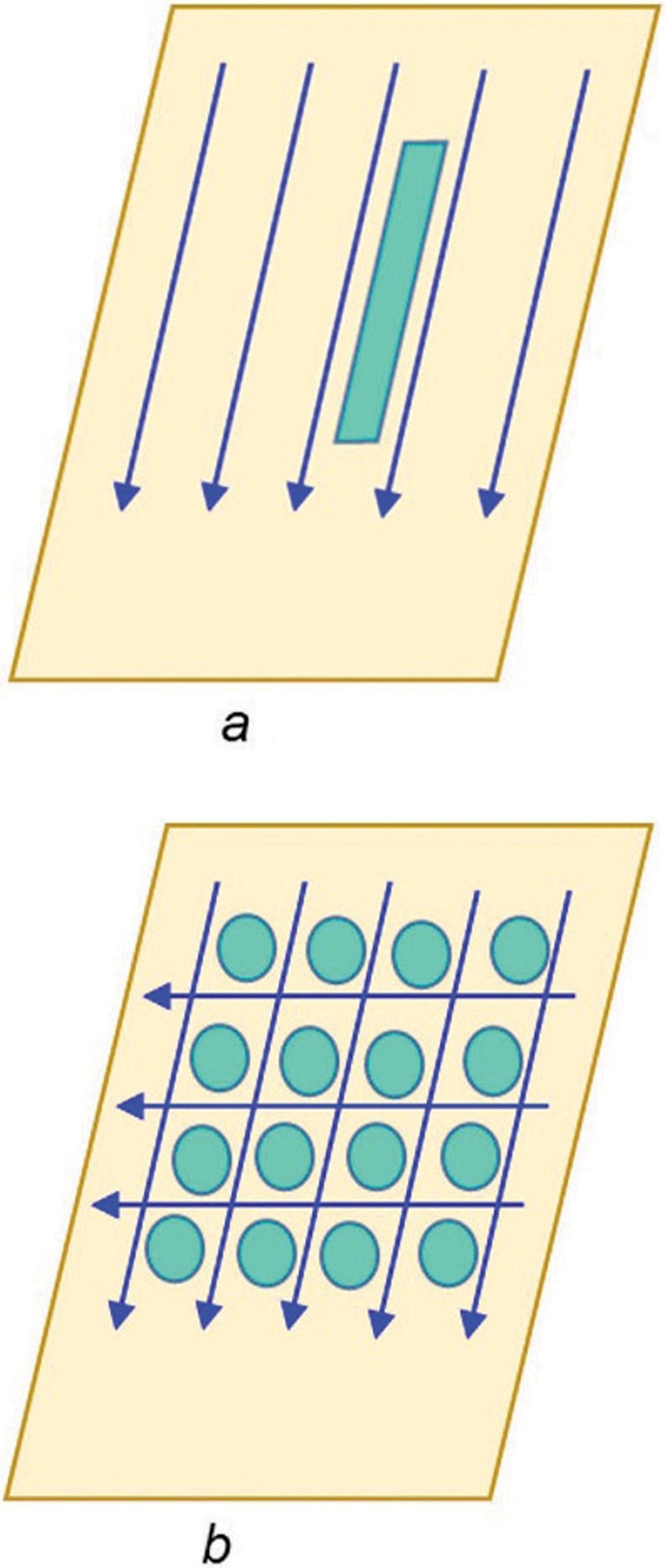
The slot will impede the current flow. Figures 3b and 3c illustrate that the thickness of the slot is not critical, but the length of it is. An obvious solution might be to place the slot parallel to the current flow, as shown in Figure 4a, to minimize its adverse effect.


 and
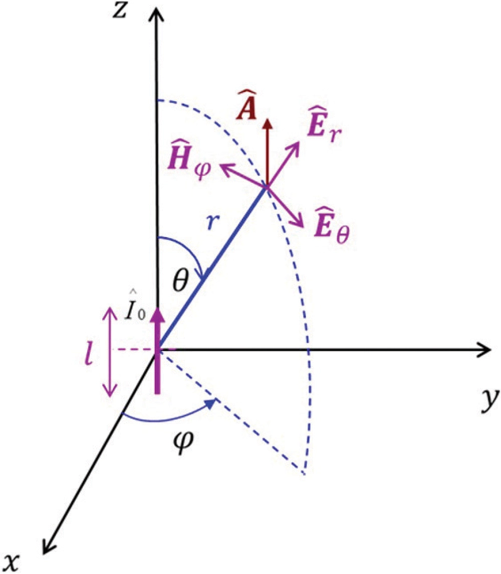
and  at an observation point P in the far field of the antenna. The medium with intrinsic impedance ηO is infinite with no other objects present.
Figure 7 shows an infinite thin flat metallic shield with a slot cut out, placed between the source and the observation point in the far field.
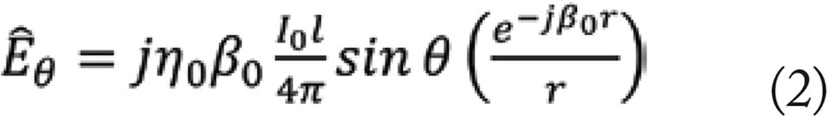
Now, the fields at an observation point P are  and
and  , as shown in Figure 7. Next, the shield is replaced by a complementary thin metallic strip of the same dimensions as the slot, as shown in Figure 8.
Now, the fields at an observation point P are  and
and  .
.
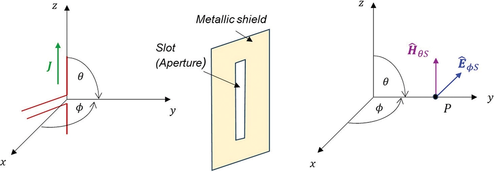
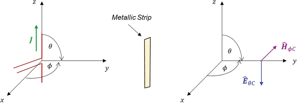


Figure 9b shows the fields at the observation point in far fields with the shield containing a slot cut out, placed between the source and the observation point. Figure 9c shows the fields with a metallic strip of the same size as the slot placed between the source and the observation point.


- Bogdan Adamczyk, “Shielding to Prevent Radiation – Part 1: Uniform Plane Wave Reflection and Transmission at a Normal Boundary,” In Compliance Magazine, June 2025.
- Bogdan Adamczyk, “Shielding to Prevent Radiation – Part 2: Uniform Plane Wave Normal Incidence on a Conducting Shield,” In Compliance Magazine, July 2025.
- Bogdan Adamczyk, “Shielding to Prevent Radiation – Part 3: Far-Field Shielding Effectiveness of a Solid Conducting Shield – Exact Solution,” In Compliance Magazine, August 2025.
- Bogdan Adamczyk, “Shielding to Prevent Radiation – Part 4A: Far-Field Shielding Effectiveness of a Solid Conducting Shield – Approximate Solutions,” In Compliance Magazine, September 2025.
- Bogdan Adamczyk, “Shielding to Prevent Radiation – Part 4B: Far-Field Shielding Effectiveness of a Solid Conducting Shield – Approximate Solutions,” In Compliance Magazine, October 2025.
- Bogdan Adamczyk, “Shielding to Prevent Radiation – Part 5: Near-Field Wave Impedance of Electric and Magnetic Dipoles,” In Compliance Magazine, November 2025.
- Bogdan Adamczyk, “Shielding to Prevent Radiation – Part 6: Near-Field Shielding Effectiveness of a Solid Conducting Shield,” In Compliance Magazine, December 2025.
- Clayton R. Paul, Introduction to Electromagnetic Compatibility, Wiley, 2006.
- C. A. Balanis, Antenna Theory Analysis and Design, Harper & Row, New York, 1982.