
lectromagnetic compatibility (EMC) has always been one of the most challenging topics to teach. Although every electrical engineer recognizes its importance, the underlying physical mechanisms – coupling, radiation, resonance, and reciprocity – are often difficult to visualize. Traditional lectures and circuit models rarely succeed in making the invisible visible.
As the Chinese philosopher Confucius said more than two thousand years ago: “I hear and I forget. I see and I remember. I do and I understand” (Figure 1). This insight forms the educational philosophy behind the EMC Demo Box, which allows students to observe and interact directly with real electromagnetic phenomena.

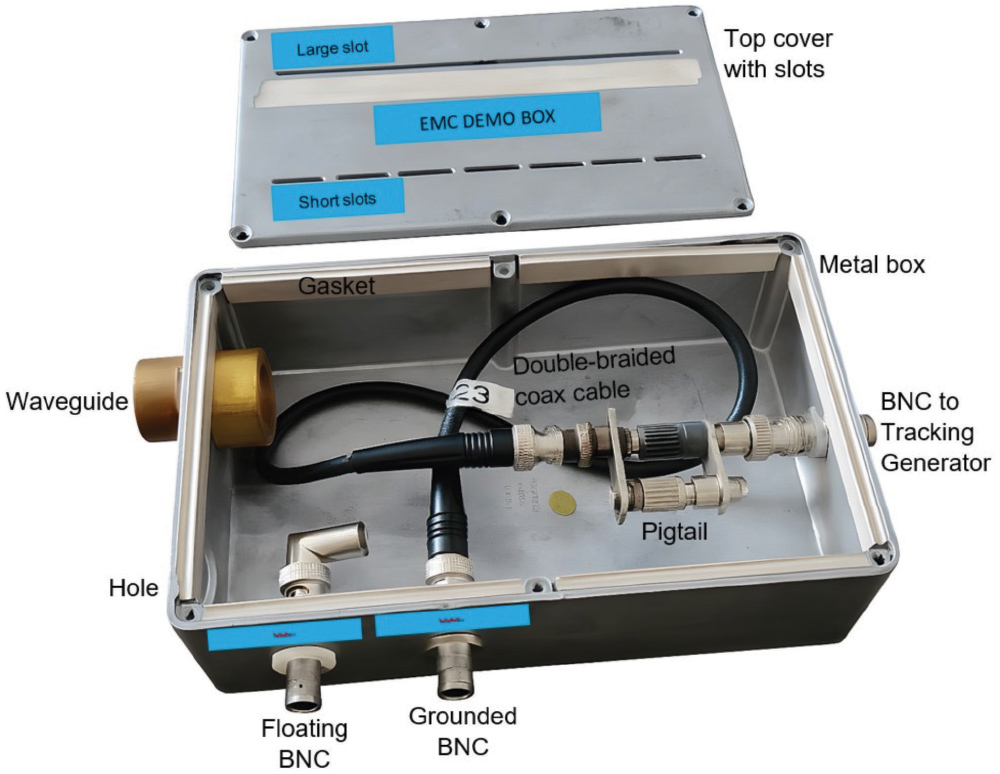
The EMC Demo Box is a compact, low-cost tool that makes electromagnetic compatibility (EMC) tangible and easy to explore. Designed for use in ordinary classrooms, it enables hands-on investigation of real EMC phenomena, such as slot radiation, common- and differential-mode coupling, grounding, and filtering, without expensive shielded facilities. Through live measurements and countermeasures, participants directly see how design choices affect emissions and immunity.
Combining radical simplicity with a strong pedagogical focus, the EMC Demo Box bridges theory and practice, deepening understanding and fostering the problem-solving skills essential for modern EMC design.
This setup allows students and engineers to explore how real electronic designs behave over a wide frequency range, from conducted to radiated effects. Most experiments show effects in the range of roughly 1 MHz to 1 GHz, where cable and slot resonances become clearly visible.
What makes the EMC Demo Box conceptually unique is its fundamental simplicity. Unlike conventional demonstration systems that rely on digital, analog, or RF circuitry, it contains no active electronics. A short coaxial cable with a pigtail, driven by the tracking generator of a spectrum analyzer, serves as a broadband electromagnetic source. This physically pure approach provides a scalable and realistic model of electromagnetic coupling and radiation across a wide frequency range.
The EMC Demo Box operates at low voltages (200 mV), ensuring a safe and student-friendly learning environment. Its simplicity and low cost make it ideal for exploring EMC behavior in an ordinary classroom, without the need for a shielded room or laboratory. With only a simple spectrum analyzer with tracking generator, all demonstrations can be performed almost anywhere, making the setup perfect for universities, training centers, and companies.
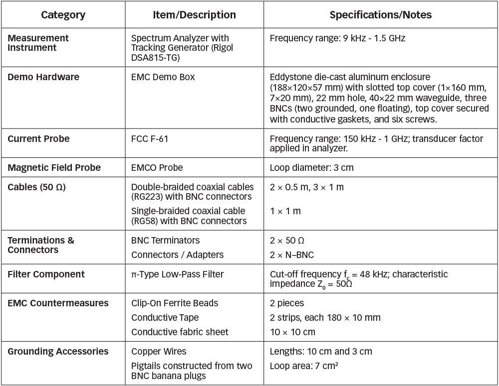
Table 1 lists all instruments and materials required to perform the EMC Demo Box demonstrations discussed in this article. The selected components represent standard laboratory tools that are widely available, making the experiments easy to reproduce in any educational or industrial environment.
- Slot radiation and leakage through apertures and waveguides
- Common-mode and differential-mode cable radiation
- Grounding and shielding effects
- Return-path and connector influence
- Impact of ferrites, filters, and conductive tapes
- Reciprocity: By swapping the generator and analyzer connections, the same setup demonstrates both emission behavior (by measuring fields from the box) and immunity behavior (by injecting signals into the box).
EMC Phenomena Demonstrated with the EMC Demo Box
- Radiation from apertures and slots
Even small apertures in a shielding enclosure act as efficient antennas when their dimensions approach half the wavelength of the interference. The demo shows how a long slot resonates and radiates strongly, and how simple countermeasures (e.g., conductive tape or shortening the slot) reduce emissions. - Cable radiation and common-mode excitation
By attaching a single-braided coaxial cable to the box, strong common-mode (CM) currents appear on the cable shield, turning the cable into an unintended antenna (cable resonances). Students can measure how far these CM currents exceed legal emission limits, and how ferrite beads, grounding, filtering, or cable choice mitigate the problem. - Shielding quality and transfer impedance
A comparison between RG58 (single-braided) and RG223 (double-braided) coaxial cables clearly shows how lower-quality shielding leads to substantially higher CM currents. This demonstrates the concept of transfer impedance (DM-to-CM conversion, ZT = VCM/IDM) and why cable construction, braid density, and connector quality directly affect EMC behavior. - Connector mounting and shield termination
The demo highlights how improper termination (e.g., a floating connector or long pigtail ground) introduces parasitic inductance and leakage paths. Measurements show how even a high-quality double-braided cable can lose most of its shielding effectiveness when its shield is routed through a pigtail. Proper 360° shield termination, by contrast, keeps interference inside the enclosure and prevents CM excitation. - Filtering
Low-pass filters effectively reduce non-functional high-frequency currents. Measurements show how both differential-mode (DM) and common-mode (CM) currents drop when appropriate filtering is applied. - Ferrite beads
Ferrite cores provide a frequency-selective impedance, typically reducing CM currents on cables by roughly 10 dB at the resonance frequencies. The demo makes this effect measurable and repeatable. - Waveguide below cutoff
A waveguide below cutoff (diameter << λ/2) provides effective shielding. If a metallic cable is routed through the waveguide, it bypasses the cutoff principle and acts as a leakage path. Only non-conductive cables (e.g., optical fiber) can pass through without degrading shielding effectiveness. - Reciprocity principle
The reciprocity principle states that the transfer function between two points is unchanged when the generator and receiver are interchanged, provided the system is linear, passive, and time-invariant. The EMC Demo Box satisfies these conditions, enabling emission–immunity reciprocity experiments with the same setup.
As part of the exercises, participants are also challenged to determine which countermeasures are required to bring the EMC Demo Box into compliance with legal EMC emission limits, reinforcing the direct link between design choices and regulatory performance.
An instructive example of what can be observed with the EMC Demo Box is shown in Figure 3. It compares the common-mode current measured on a coaxial cable (type RG223) in two configurations, one with the cable shield floating and the second with the shield connected through a proper 360-degree grounding termination to the metal box. The measurement was performed using a current probe and a spectrum analyzer in the frequency range from 30 to 300 MHz.

This simple experiment makes visible how an improper shield connection can drastically increase common-mode emissions, an effect that is often underestimated in practice but becomes immediately clear when demonstrated with the EMC Demo Box.
In its current form, the EMC Demo Box effectively demonstrates fundamental EMC principles from 1 MHz to 1 GHz, covering common emission and immunity challenges. Its core design, a metal enclosure with controlled apertures and coupling paths, is inherently scalable. With the simple substitution of a spectrum analyzer featuring a tracking generator capable of operating up to 6 GHz, the demonstration platform can be seamlessly extended to higher frequencies, making the EMC Demo Box a versatile and inherently future-proof tool for both current and emerging EMC applications.
This hands-on approach bridges the gap between theory and physical reality, transforming EMC from a compliance problem into a design discipline. Through this practical, experiment-driven approach, participants not only solidify their theoretical knowledge but also develop critical thinking and analytical skills essential for diagnosing and solving complex EMC challenges in real-world design.
The same setup is also used in industry-oriented sessions, not only for engineers but also for management awareness training. By witnessing in real-time how a small mechanical detail, like a cable shield connection, can cause or suppress interference by 30 dB or more, decision-makers gain immediate and tangible insight into why EMC considerations must begin early in the design process.
Feedback from participants confirms the educational value of the EMC Demo Box. As an example, an engineer reported that “after completing the hands-on exercises, the theory suddenly made sense, we could see the real behavior of currents and fields that had previously been just formulas.”
The educational approach of the EMC Demo Box is supported by established pedagogical research and trends in EMC education. The philosophy of “learning by doing,” succinctly captured by Confucius, is strongly advocated in modern engineering education.1
Furthermore, the value of simple, hands-on tools for teaching EMC fundamentals has been demonstrated by leading educators in the field.2, 3 The EMC Demo Box aligns with this consensus, providing a versatile and accessible platform to implement these proven educational strategies.
Developed from decades of EMC training and workshop experience, the EMC Demo Box offers something no algorithm can provide: the human connection between cause and effect. It shows that true EMC competence emerges not only from knowledge, but from direct interaction with the physical world.
The Demo Box also serves as a counterweight to AI-driven education. It turns learning into active exploration: students form hypotheses, make measurements, and draw conclusions. They learn to think and reason like engineers, rather than simply producing ready-made answers generated by a machine.
Ultimately, the EMC Demo Box trains skills that no AI can provide: critical thinking, judgment, and responsibility. These human qualities are essential for designing safe, reliable, and compliant technology, and for keeping humans firmly in the loop as AI continues to reshape technical practice.
As Confucius said: “What I do, I understand.”
That simple wisdom continues to guide how we teach and how we truly learn the art of electromagnetic compatibility. Even in an age of artificial intelligence and digital automation, it is through direct experience – through doing, observing, and understanding – that real engineering insight is born. True understanding in EMC cannot be written; it must be experienced.
The EMC Demo Box is currently used in several university and industry training programs to bring these principles to life. Readers who wish to explore the full set of hands-on exercises and demonstrations are invited to consider one of the following specialized EMC courses:
- High Tech Institute – Electromagnetic Compatibility Design Techniques
- High Tech Institute – EMC Course for Mechatronic Engineers
- PAO – Electromagnetic Compatibility (EMC)
- Prince, M., “Does Active Learning Work? A Review of the Research,” Journal of Engineering Education, 2004.
- Leferink, F., “Educating Electromagnetic Effects using Printed Circuit Board Demos,” EMC Conference, Kyoto, Japan, 2009.
- Degraeve, A., et al., “Teaching EMC using an EMC demonstration unit,” IEEE/APEMC Symposium, Singapore, 2018.