
ecause virtually all electronic devices and electrical apparatus require safety certification, manufacturers must submit samples of their products to compliance agencies and regulatory authorities to ensure they meet global standards.
This article gives an overview of the many safety standards required for certification and how advanced hipot testers have evolved to speed and simplify the compliance process. It also discusses the critical pre-testing setup and safety procedures required to ensure user safety. Finally, it describes the four types of essential hipot tests, dialectic withstand, insulation resistance, ground continuity, and ground bond testing, conducted during final production as well as the test results to look for.
During the production phase of product development, products destined for sale in the U.S. market are typically sent to Nationally Recognized Testing Laboratories (NRTLs) for compliance testing. NRTLs provide services to certify compliance with the relevant standard(s) and regularly inspect the testing equipment and facilities.
The compliance evaluation conducted by an NRTL typically investigates two key areas of a product, as follows:
- Construction—Mechanical construction, spacing, clearances, etc.; and
- Safety—To assure safe operation, even under high-stress conditions.
The details of what constitutes an NRTL-certified product depend on the specific standard (or standards) applicable to that product. For products that will be sold and used in jurisdictions outside the U.S., the requirements of different standards may be applicable, potentially complicating the process of achieving global access.
In an effort to address this challenge, efforts are ongoing to harmonize standards internationally. An example is IEC 61800-5-1, a standard developed by the International Electrotechnical Commission (IEC) that addresses the safety aspects related to electrical, thermal, and energy in adjustable speed electrical power drive systems. In the U.S., the requirements of IEC 61800-5-1 have effectively replaced those of UL 508C, which has been withdrawn and superseded by UL 61800-5-1.
Hipot testing has long been a standard procedure for various types of equipment. Hipot testers get their name from the “high potential” (high voltage) that they produce in order to perform dielectric withstand and insulation resistance tests. Many hipot testers also provide accurate, low-resistance measurements and low-resistance/high-current outputs to test ground resistance and ground bond integrity.
The early commercial hipot tester was not much more than a step-up transformer used to adjust an applied voltage in stepped increases over prescribed time segments to test for leakage or component breakdown. However, this legacy method could easily lead to incorrect results when leakage current causes the voltage output from a high-impedance transformer source to drop.
In contrast, today’s most advanced hipot testers utilize electronic source technology to assure compliance with IEC-61010, which explicitly requires that “the voltage test equipment shall be able to maintain the required voltage for the specified period of time.”
By its very nature, electrical safety testing involves the use of high voltages and requires test operators to follow strict adherence to safety procedures. Operators should understand that high voltages are dangerous and that care must be taken to avoid contact with energized circuits. The importance of having trained personnel as the first step in ensuring a safe testing environment can’t be overstated.
The next step is determining where the test station will be located. The test area should be isolated from the factory assembly area and located away from routine foot traffic to help ensure the safety of those who occasionally come near the test station. In addition, operator distractions should be kept to a minimum and the area should be conspicuously marked with internationally approved signage, such as “DANGER – HIGH VOLTAGE.”
During testing, the hipot tester itself should have indicator lights to denote when high voltage is present. There should be ample and reliable power supplied to the test station. Verify that the power wiring meets electrical code requirements for polarization and grounding. Always use an outlet that has a properly connected protection ground and make sure this ground has been tested to ensure a low impedance path to the panel ground and earth bonded ground.
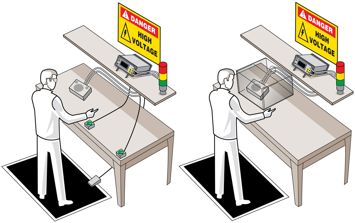
Figure 2a/2b illustrates two alternative approaches to the setup of a benchtop hipot test. In Figure 2a, the operator is wearing safety glasses, and the device under test (DUT) is placed on the test bench equipped with a combination of palm switches and a footswitch to prevent the operator from making direct contact with the DUT while testing is underway. As a practical matter, the use of palm switches is typically restricted to short-duration tests done on a repetitive basis with a series of DUTs. If this test setup is used for longer tests, operators often find a way to bypass the palm switches, thereby defeating their intended purpose of protecting the operator.
Figure 2b shows the DUT placed under a protective cover with an interlock to isolate the operator during the test. The use of an enclosure is a more reliable means of assuring operator safety, particularly when testing requires longer time periods. More elaborate test stations can include a hipot tester interlock as well.
One safety method that utilizes the interlock is a light curtain, which is an infrared light beam that opens the interlock if anyone interrupts any part of the beam. The output of the light curtain is connected to the interlock terminal on the hipot tester. If the interlock is open, high voltage is immediately terminated. The light curtain is placed in between the hipot tester or the DUT and the operator. For the operator to touch the high voltage, they would have to pass through the light curtain, triggering the opening of the interlock and terminating the high voltage.
If the hipot is placed behind a light curtain, a method must be available to initiate the test, and a footswitch is an easy solution. But keep in mind that the test space must be designed to prevent anyone from reaching the high voltage by going around the light curtain.
Operator injury may result if the hipot tester is not properly connected to an earth ground. The work area and bench surface should consist of non-metallic materials, which means that metalwork surfaces should be avoided, and metal objects should not be placed between the operator and the DUT. All other metal objects should either be grounded or placed outside of the test area altogether. An ESD mat is not a recommended platform for a test station, as it may cause erroneous readings for leakage and is unnecessary in this application.
The test equipment should also provide for immediate and safe removal of the output voltage using internal discharge circuity, either at the conclusion of the test or if the test is interrupted. Never remove power for the hipot tester. If there is a power interruption, use extreme care in any contact with the DUT. The safest approach is to leave the DUT connected to the hipot tester until power is restored and the tester can conduct its discharge function.
The test station should have sufficient space for the tester and the DUT without the operator having to reach over the DUT to access the tester. The tester should be at least three inches away from the wall to provide proper airflow for the unit. Ideally, the DUT should be isolated from the operator and the tester. For larger DUTs, which are wheeled to the test station, the cart should be non-conductive and have locking wheels. (This also applies if the tester needs to be wheeled to the DUT.) Keep the area clean and neat, and arrange the equipment so that it is easy and safe for the operator to use.
There are many safety features that can be added to the test station to prevent the operator from encountering high voltage, such as guards or enclosures. When placed around a DUT, guards or enclosures should be non-conducting and be equipped with safety interlocks that interrupt all high voltages when open. Interlocks should be arranged so that operators are never exposed to high voltages under any conditions.
In addition, it is easy to implement circuit palm switches that prevent the operator from encountering high voltage during testing. The basic operation of a palm switch requires the operator to use both hands to initiate a test with, potentially, a footswitch to activate the test. If one or both hands are removed from the switches while testing, the test is immediately stopped. The switches are placed directly in front of the operator and spaced shoulder-width apart. Spacing the switches in this way prevents an operator from trying to press both buttons down with one hand or object.
No high voltage can be applied to the output terminals and DUT until both switches are pressed simultaneously. The operator cannot touch the DUT or test leads if both hands are on the palm switches. The palm switches are connected to the digital I/O on the hipot tester. Only when the switches are in the down position is the start function enabled. Once one switch goes up, the safety interlock is enabled, terminating the output voltage of the hipot test. This method is safe, quick, and effective.
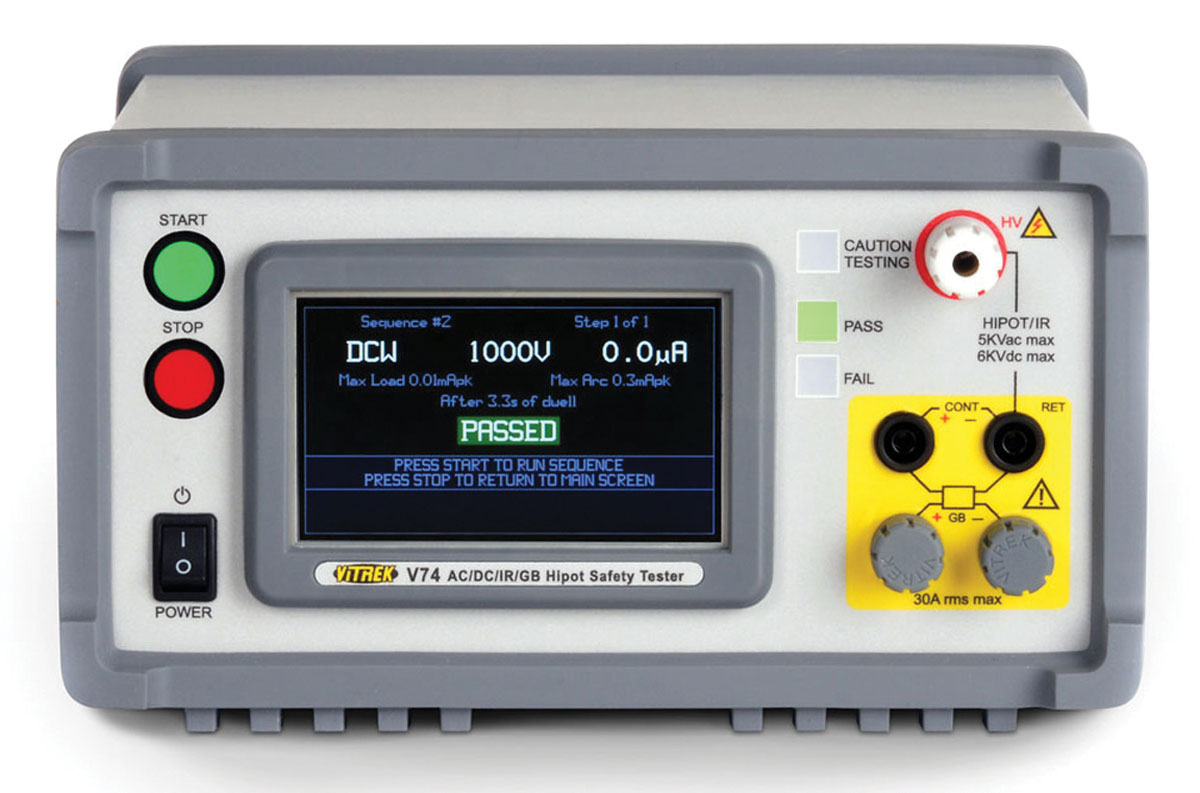
On a regular basis, typically at the start of every shift, the tester itself should be checked by connecting the tester to both PASS and FAIL samples. These samples should be designed to confirm the proper operation of the tester based on the type(s) of tests to be conducted (hipot, insulation resistance, ground resistance, or ground bond). Once all of the connections are made, and the prescribed test procedure is selected, the operator should confirm that all test parameters specified in the testing documentation are displayed on the tester screen. Operation of the test can then be conducted, keeping in mind the safety considerations described previously.
Hipot testing during production is performed to:
- Assure compliance with safety agency labeling requirements;
- Detect defective components or assembly flaws; and
- Reduce the incidence of latent field failures and the attendant warranty costs.
Once in production, products must be 100% tested to confirm compliance with the related agency certifications and safety standards. Production tests are less stringent than initial certification testing but will generally include basic dielectric withstand and shock hazard (leakage) tests.
Plug-connected devices will also be subjected to ground resistance and ground bond tests if required by the applicable standard. Electrical motors, transformers, and other such devices will likely include insulation resistance tests.
Periodic inspection and calibration of test equipment is a standard requirement to maintain NRTL certification for the product being produced. This inspection will include a check of hipot instrument calibration certification. This “cal cert” is typically required to be renewed on an annual basis. (NRTLs require compliance certification with ISO 17025.) Another common requirement prescribed by most NRTLs is a daily functional test of the hipot equipment.
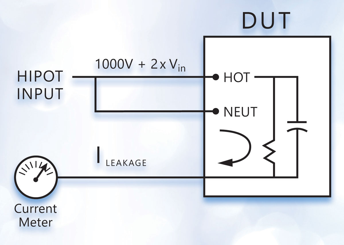
The basic hipot test applies a high voltage from the conductors to the chassis of the DUT. This test is often referred to as dielectric test or voltage withstand test. Its purpose is to confirm that the insulation and isolation of the non-conducting surfaces from the operating voltage are sufficient to avoid a shock hazard. The typical specification for this test is 1000V + 2x normal operating voltage.
Both AC and DC hipot tests are possible and, in general, the test should use the same type of voltage as would be used during normal operation. However, if a DC hipot test is used on an AC circuit, the hipot voltage should be two times the peak, that is (2 x 1.4 x RMS) + 1000V (see Figure 3).
Depending on the applicable standard, units will pass this test if either:
- The leakage current measured is less than the maximum allowable current; or
- No breakdown occurs, i.e., there is no sudden and uncontrolled flow of current.
In the case of double-insulated products, higher voltages are often specified in the test standard. In addition, this class of device typically requires special fixturing to connect the non-conductive outer shell to a conductive element.
Defects that are often detected with the hipot test include contamination (e.g., dirt, debris, etc.) and lack of proper spacing (creepage and clearance) of components. Creepage is measured across surfaces, while clearance is the air gap between components. Contamination would likely cause an unacceptable level of leakage current. Clearance problems can result in a breakdown.
Desirable hipot tester features for dielectric withstand testing include:
- Adjustable maximum output voltage:
- 5KV is adequate for many applications
- Higher voltages (up to 30KV) may be required
- AC and DC outputs
- Excellent regulation – both line and load
- Controllable ramp rates, dwell times, and discharge features
- Phase angle measurement of leakage current – capacitive coupling detection
- Some standards allow for in-phase and quadrature currents to be measured separately. Leakage current due to capacitive coupling may not be a safety concern
- Min/max pass/fail current limits:
- Separate limits during ramp
- Programmable multichannel testing
Insulation resistance testing is likely to be required in motor winding, transformer winding, and other applications involving cabling or insulated wire. Insulation resistance testing typically involves confirming that the resistance exceeds a defined high resistance value.
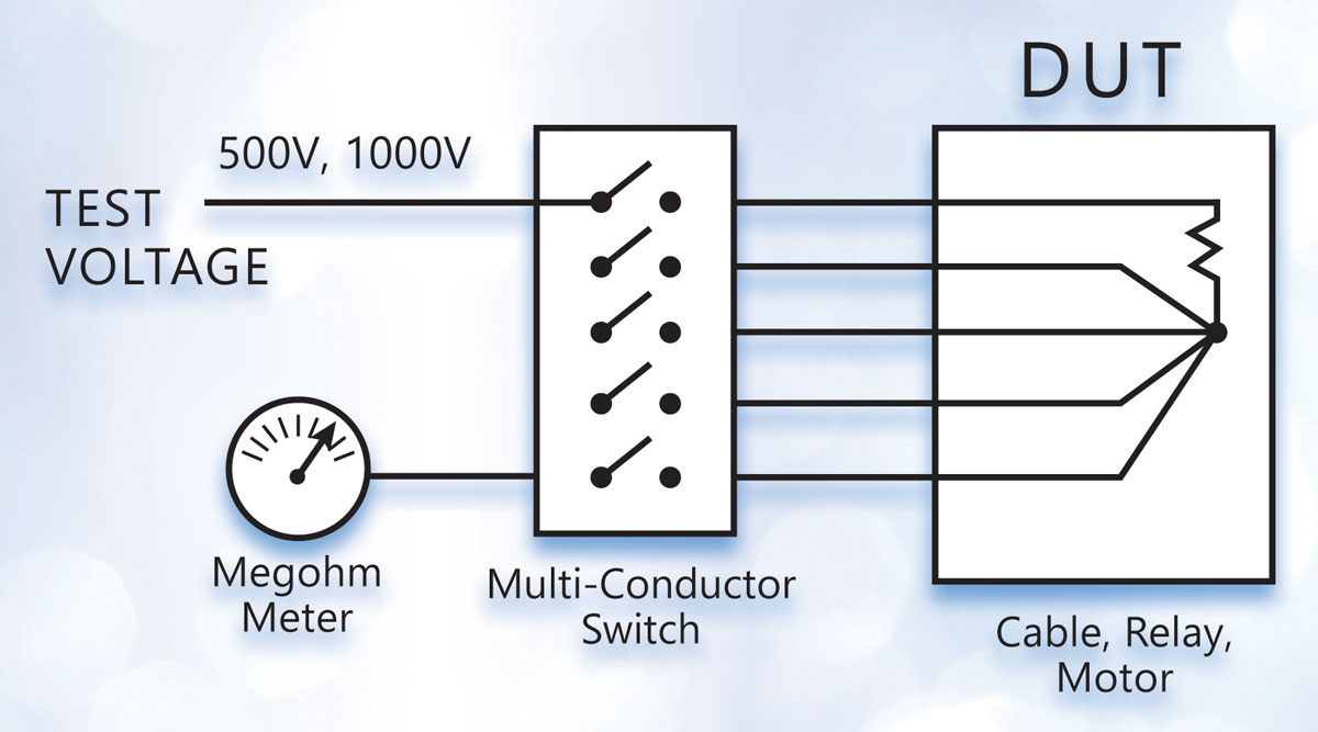
In many instances, insulation resistance needs to be measured between several conductors. Examples include cable/connector assemblies, multiconductor cables, and relays. To make this measurement, all the conductors except one are shorted together, and the test voltage is applied from the remaining conductor across the bundled ones. Each wire is then tested in this fashion (see Figure 4.)
Desirable hipot tester features for insulation resistance testing include:
- Wide range of selectable test voltages
- Accurate/repeatable high-resistance measurement
- Programmable high voltage switching accessory
- Multichannel programmable testing
- Pass on steady and increasing voltage
Ground continuity testing is performed to confirm that the conductive chassis of a device is safely connected to the earth ground pin on the power plug. This assures protection against shock hazards even if the equipment suffers an internal short to the chassis. The current would be shunted via the ground wire and would likely trip the breaker or blow the fuse.
Ground continuity is performed by applying a low current (e.g., 50 mA) and calculating the resistance from the ground pin on the power plug to selected locations on the exposed surfaces of the DUT.
Desirable hipot tester features for ground continuity testing include:
- Accurate, repeatable low resistance meter
- Plug adaptor accessory to speed testing
Whereas ground continuity measures the resistance of the safety ground connection, the ground bond test assures the integrity of the connection. Using the same test setup, a high current is passed through the circuit. If the ground bond is solid, the current passes without a change in resistance.
Desirable hipot tester features for ground bond testing include:
- Accurate high-current source
- Programmable test currents and test times
- Plug adaptor accessory to speed testing
- 4-wire milliohm meter – providing a Kelvin connection for highly accurate low resistance measurement
Hipot testing is an important final step in the production process for most electrical and electronic equipment. With programmable features and advanced functionality, today’s hipot testers simplify electrical safety testing. But before commencing testing, manufacturers should be aware of the many updated safety certification standards and their requirements. And test operators must ensure upfront that they have set up a safe testing environment and fully understand the applicable testing protocols.
